


MIM-1T1/MIM-2T1/MIM-4T1/MIM-1T1-F/MIM-2T1-F/MIM-4T1-F Modules 91
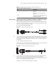
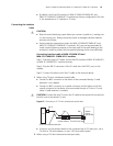
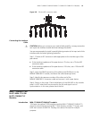
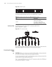
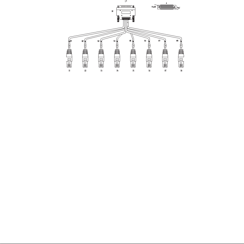
Figure 102 120-ohm 8E1 conversion cable
Connecting the Interface
Cable
c
CAUTION: Before you connect a port, read its label carefully; a wrong connection
can impair the interface module and even damage the device.
You are recommended to install a special lightning arrester at the input end of the
interface cable for better lightning protection.
Step 1: Choose an 8E1 conversion cable appropriate to the interface type of the
peer device.
■ If the interface impedance of the peer device is 75-ohm, use a 75-ohm 8E1
conversion cable.
■ If the interface impedance of the peer device is 120-ohm, use a 120-ohm 8E1
conversion cable.
Step 2: Insert the DB-68 connector of the cable to the DB-68 port on the
MIM-8E1/MIM-8E1-F module, and fasten the cable fastening screws.
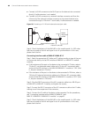
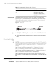
Step 3: Identify the sequence number of the other end of the
MIM-8E1/MIM-8E1-F conversion cable and connect it with a peer device.
Step 4: Power on the router. Check the behavior of the LINK LED on the module
panel. It is OFF when fault has occurred on the link and signal is out of
synchronization. In this case, please check the link.
MIM-1T1/MIM-2T1/MI
M-4T1/MIM-1T1-F/MI
M-2T1-F/MIM-4T1-F
Modules
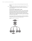
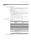
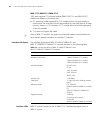
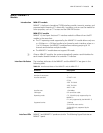
Introduction MIM-1T1/MIM-2T1/MIM-4T1 module
1/2/4-port channelized T1/PRI interface module (MIM-1T1/MIM-2T1/MIM-4T1)
serves to transmit/receive and handle T1 data streams, provide CT1 access, and
fulfill the function of ISDN PRI. Thereby, one card can be used for multiple
purposes.