


122 CHAPTER 3: MULTIFUNCTIONAL INTERFACE MODULES
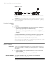
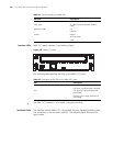
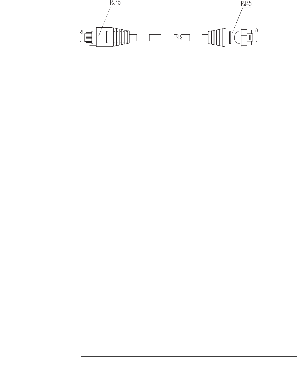
Figure 138 T1 cable
For the pinouts of T1 cables, see Low-End and Mid-Range Series Routers Cable
Manual.
c
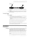
CAUTION: The corresponding cables are not included in the standard shipment
package of MIM-2VT1. Please order them together with MIM-2VT1. By default,
they are not supplied.
Connecting the Interface
Cable
c
CAUTION:
■ You should connect a cable to the port with the correct mark. Misplugging is
prone to impair the card and even damage the router.
■ When using T1 cable outdoors, you are recommended to install a special
lightning arrester on the input end of the cable in order to avoid lightning more
effectively.
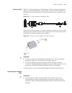
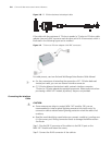
If the MIM has been properly installed, follow these steps to connect the cable:
Step 1: Plug one end of T1 cable into the RJ45 connector of MIM-2VT1.
Step 2: Connect the other end of T1 cable to the peer device;
Step 3: Check the status of LINK LED on the MIM-2VT1 panel: OFF means the link
is not connected. In the latter case, check the line.
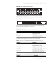
MIM-1VE1 Module
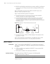
Introduction 1-port E1 voice interface module (MIM-1VE1) can handle dense voice signals in
VoIP system. It provides a CE1/PRI/R2 port, allowing the access of 30 channels of
voice signals.
n
■ VCPM is provided to users together with MIM-1VE1. Users can select VPM
module as needed.
■ VPM module is installed on the main board of MIM-1VE1.
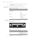
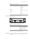
Interface Attributes The interface attributes of MIM-1VE1 are given in the following table.
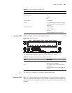
Table 82 Interface attributes of MIM-1VE1
Attribute Description
Connector DB-15