


SIC-1GEC 43
c
CAUTION: SIC-1GEC uses COMBO interface; therefore it cannot support fiber and
electrical interfaces at the same time. When the router is powered on, the
electrical interface takes effect by default. If you want to use a fiber interface, use
a command to configure it.
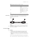
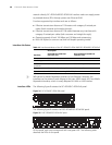
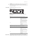
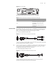
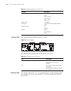
Interface LEDs The following figure illustrates the SIC-1GEC panel.
Figure 37 SIC-1GEC panel
The following table describes the electrical interface LEDs on the left of the
SIC-1GEC panel.
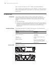
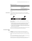
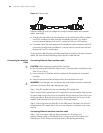
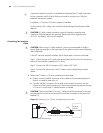
Interface Cable Normally, category-5 twisted pair cable is adopted to connect the 10BASE-T
/100BASE-TX Ethernet interface to the Ethernet, as shown in the following figure:
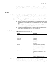
Table 18 LEDs for the electrical interface on the left of the SIC-1GEC panel
LED Description
LINK ON means carrier signal is received;
OFF means no carrier signal is
received;
Green: Data is being received and
transmitted at a speed of 1000 Mbps.
Yellow: Data is being received and
transmitted at a speed of 100/10
Mbps.
ACT OFF: No data is being received and
transmitted;
Blinking: Data is being received and
transmitted.
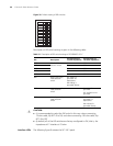
Table 19 LEDs for the fiber interface on the right of the SIC-1GEC panel
LED Description
LINK ON means carrier signal is received;
OFF means no carrier signal is
received;
Green: Data is being received and
transmitted at a speed of 1000 Mbps;
Yellow: Fault.
ACT OFF: No data is being received and
transmitted;
Blinking: Data is being received and
transmitted.