


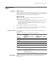
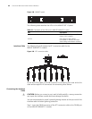

96 CHAPTER 3: MULTIFUNCTIONAL INTERFACE MODULES
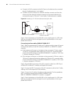
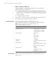
Figure 108 MIM-8T1 panel
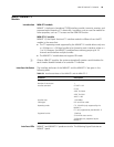
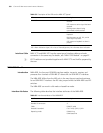
The following table describes the LEDs on the MIM-8T1/8T1-F panel:
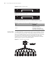
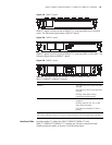
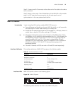
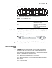
Interface Cable The following figure illustrates the 8T1 conversion cable for the
MIM-8T1/MIM-8T1-F module.
Figure 109 8T1 conversion cable
At one end of the cable is a DB-68 connector for connecting the router and at the
other end are eight RJ-45 connectors for connecting other devices.
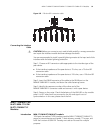
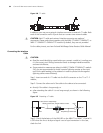
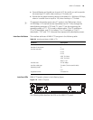
Connecting the Interface
Cable
c
CAUTION: Before you connect a port, read its label carefully; a wrong connection
can impair the interface module and even damage the device.
You are recommended to install a special lightning arrester at the input end of the
interface cable for better lightning protection.
Step 1: Insert the DB-68 connector of the 8T1 conversion cable to the DB-68 port
on the MIM-8T1/MIM-8T1-F module.
Table 55 Description of the LEDs on the MIM-8T1/MIM-8T1-F panel
LED Description
LINK OFF means no link is present; ON
means a link is present.
ACTIVE OFF means no data is being
transmitted or received. ON means
data is being transmitted or received.