


134 CHAPTER 3: MULTIFUNCTIONAL INTERFACE MODULES
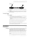
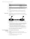
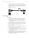
Step 2: Insert the DB68 connector at one end of the 4E1/8E1 conversion cable to
the DB68 interface on the MIM-IMA-4E1/MIM-IMA-8E1 module, and fasten the
cable retaining screws.
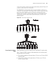
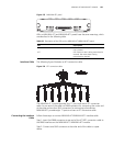
Step 3: Identify the sequence numbers of the connectors at the other end of the
4E1/8E1 conversion cable and connect one connector (or a pair of connectors) to
the peer device.
Step 4: Power on the router. Check the status of the LINK LED on the
MIM-IMA-4E1/ MIM-IMA-8E1 module panel. OFF means the line has problem and
signal is out of synchronization. In this case, please check the line.
MIM-IMA-4T1/MIM-IM
A-8T1 Module
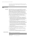
Introduction The 4-port/8-port T1 ATM inverse multiplexing interface module
(MIM-IMA-4T1/MIM-IMA-8T1) provides four/eight T1 interfaces that support the
IMA technology. Their network application is similar to that of the
MIM-IMA-4E1/MIM-IMA-8E1 module.
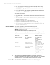
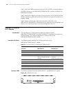
Interface Attributes The following table describes the interface attributes of the
MIM-IMA-4T1/MIM-IMA-8T1 module.
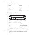
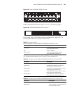
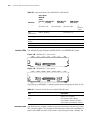
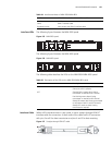
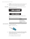
Interface LEDs The following figures illustrate the MIM-IMA-4T1 and MIM-IMA-8T1 panels.
Figure 152 MIM-IMA-4T1 panel
Table 92 Interface attributes of MIM-IMA-4T1/MIM-IMA-8T1
Attribute
Description
MIM-IMA-4T1 MIM-IMA-8T1
Connector DB68
Number of connectors 1
Interface standard ITU-G.703, ITU-G.704
Cable type 4T1 conversion cable
(100-ohm straight-through
shielded)
8T1 conversion cable
(100-ohm
straight-through shielded)
Max transmission distance 150 m (492.1 ft.)
Operating mode ATM T1 independent link/IMA bundle mode
Supported service AAL5
Protocol PPPoA, PPPoEoA, IPoA, IPoEoA
Transmission rate CBR/VBR-rt/VBR-nrt/UBR