


216 CHAPTER 4: FLEXIBLE INTERFACE CARDS
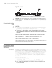
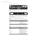
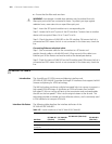
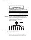
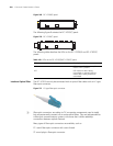
Figure 264 FIC-IMA-8T1 panel
The following table describes the LEDs on the FIC-IMA-4T1/FIC-IMA-8T1 panel:
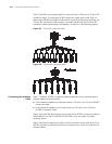
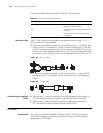
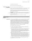
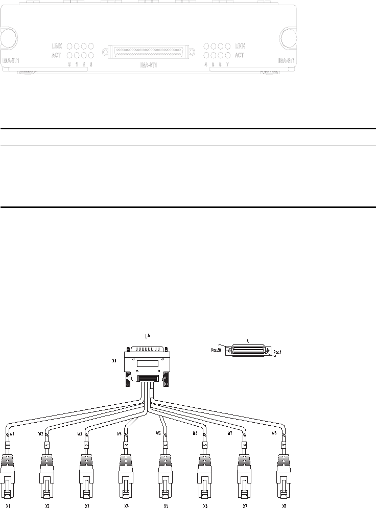
Interface Cable The FIC-IMA-4T1/FIC-IMA-8T1 card provides four/eight T1 ports and uses a
4T1/8T1 conversion cable for connection. At one end of the cable is a DB-68
connector for connecting the router and at the other end are four/eight RJ-45
connectors for connecting other devices.
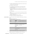
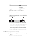
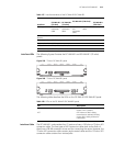
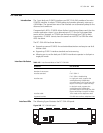
The following figure illustrates an 8T1 conversion cable.
Figure 265 8T1 conversion cable
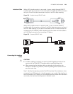
Connecting the Interface
Cable
Step 1: Insert the DB-68 connector of the 4T1/8T1 conversion cable to the DB-68
port on the FIC-IMA-4T1/FIC-IMA-8T1 card.
Step 2: Connect one RJ-45 connector at the other end of the cable to the peer
device to be connected.
Step 3: Power on the router. Check the behavior of the LINK LED on the card
panel: OFF means the line has problem. Check the line status in this case.
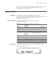
Table 160 LEDs on the FIC-IMA-4T1/FIC-IMA-8T1 panel
LED Description
LINK OFF means no link is present; ON means a
link is present.
ACT OFF means no data is being transmitted or
received; blinking means data is being
received or transmitted.