


FIC-2FXS/FIC-2FXO/FIC-2E&M and FIC-4FXS/FIC-4FXO/FIC-4E&M 195
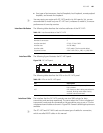
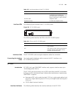
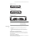
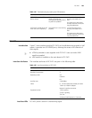
Figure 238 FIC-4FXS panel
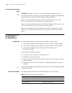
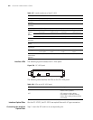
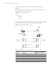
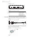
The following figure illustrates the FIC-4FXO panel:
Figure 239 FIC-4FXO panel
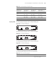
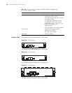
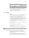
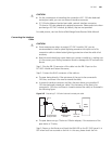
The following figure illustrates the FIC-4E&M panel:
Figure 240 FIC-4E&M panel
Interface Cable
n
■ RJ-45 receptacles on the FIC-FXO/FIC-FXS/FIC-E&M cards adopt RJ-45
connectors.
■ The standard equipping package for the FIC-2FXS/FIC-2FXO and the
FIC-4FXS/FIC-4FXO includes the appropriate number of regular telephone
cables.
Interface cables for the FIC-FXS/FIC-FXO cards
Interface cables for FIC-2FXS/FIC-2FXO and FIC-4FXS/FIC-4FXO are telephone
cables with ferrite core. For cable pinouts, see Low-End and Mid-Range Series
Routers Cable Manual.
Interface cables for FIC-E&M cards
E&M cards available with H3C Series Routers support Bell I, II, III, V switches, and
use 2-wire and 4-wire voice implementations.
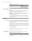
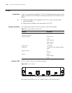
Table 140 LEDs on the FIC-FXS/FIC-FXO/FIC-E&M panel
LED Description
LINK OFF means no link is present.
ON means a link is present.
ACT OFF means the channel is idle.
ON means there is call activity.