


46 CHAPTER 2: SMART INTERFACE CARDS
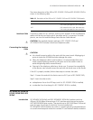
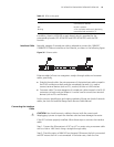
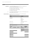
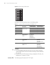
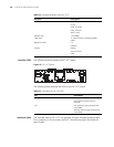
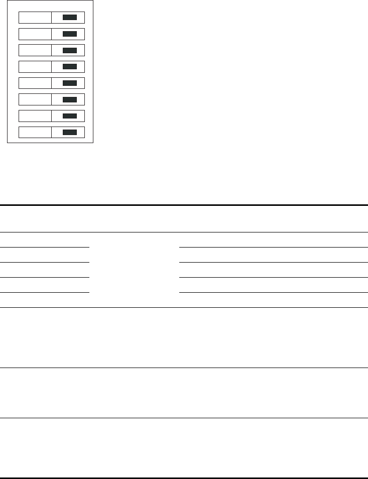
Figure 39 Default setting of DIP switches
Description of DIP switch settings is given in the following table:
c
CAUTION:
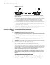
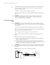
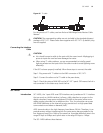
■ It is recommended to select the DIP switch in this way: when connecting
75-ohm cable, flip BIT1-8 to ON, and when connecting 120-ohm cable, flip
BIT1-8 to OFF.
■ By default, all of the DIP switches are factory-configured to ON, that is, the
impedance of E1 interface is 75-ohm.
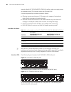
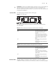
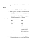
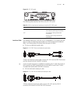
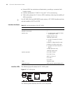
Interface LEDs The following figure illustrates the SIC-1VE1 panel.
Table 21 Description of DIP switch settings of SIC-ERRI/SIC-1E1-F
DIP Description
Configuration of
75-ohm impedance
Configuration of
120-ohm impedance
1BIT 75-ohm/120-ohm
selection switch
ON OFF
2BIT ON OFF
3BIT ON OFF
4BIT ON OFF
5BIT ON OFF
6BIT RxRing grounding
mode selection
switch
OFF: RxRing is
grounded via
capacitance.
ON: RxRing is
grounded directly.
-
7BIT RxShield grounding
mode selection
switch
- ON: RxShield is
grounded.
OFF: RxShield is not
grounded.
8BIT SxShield grounding
mode selection
switch
- OFF: RxShield is
grounded via
capacitance
ON: RxShield is
grounded directly.
on
1
2
3
4
5
6
7
8