


SIC-1BS/SIC-2BS&SIC-1BU/SIC-2BU 57
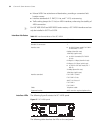
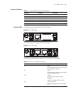
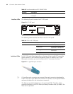
The following table describes the LEDs on SIC-1BS/SIC-2BS and SIC-1BU/SIC-2BU
panels.
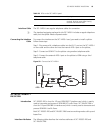
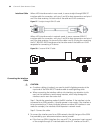
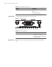
Interface Cable Both SIC-1BS/SIC-2BS and SIC-1BU/SIC-2BU use the telephone cable with ferrite
core.
c
CAUTION: The corresponding cables of SIC-1BS/SIC-2BS and SIC-1BU/SIC-2BU are
included in their standard shipment packages.
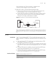
Connecting the Interface
Cable
c
CAUTION:
■ When connecting the interface cable, pay attention to the mark on the
interface to avoid wrong insertion, which may damage the interface card or
even the router host.
■ If outdoor cabling is involved, you need to install a lightning arrester at the
input end of the SIC-BU/SIC-BS interface cable to avoid lightning strike.
After the interface card is properly installed, follow these steps to connect the
cable.
Step 1: Verify the type of the ISDN line provided by your telecommunications
service provider.
Step 2: Connect the cable.
■ For SIC-1BS/SIC-2BS
If the line is an ISDN U-interface line, use an NT1 for conversion. Insert one end of
the telephone cable with ferrite core into the BRI S/T interface of SIC-1BS/SIC-2BS,
and the other end to NT1.
If the line is an ISDN S/T interface line, insert one end of the telephone cable with
ferrite core to the BRI S/T interface of SIC-1BS/SIC-2BS, and connects the other
end with the ISDN S/T interface line.
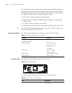
Table 30 LEDs on SIC-1BS/SIC-2BS and SIC-1BU/SIC-2BU panels.
LED Description
B1 OFF indicates the B1 channel is idle.
Blinking indicates the B1 channel is being
used for data communication.
B2 OFF indicates the B2 channel is idle.
Blinking indicates the B1 channel is being
used for data communication.
ACT OFF indicates the inactive state. Steady ON
indicates the active state.
ON OFF indicates interface card is powered off.
ON indicates the interface card is powered
on.