


FIC-1ATM-OC3MM/FIC-1ATM-OC3SM/ FIC-1ATM-OC3SML 189
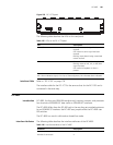
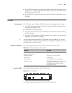
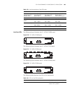
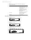
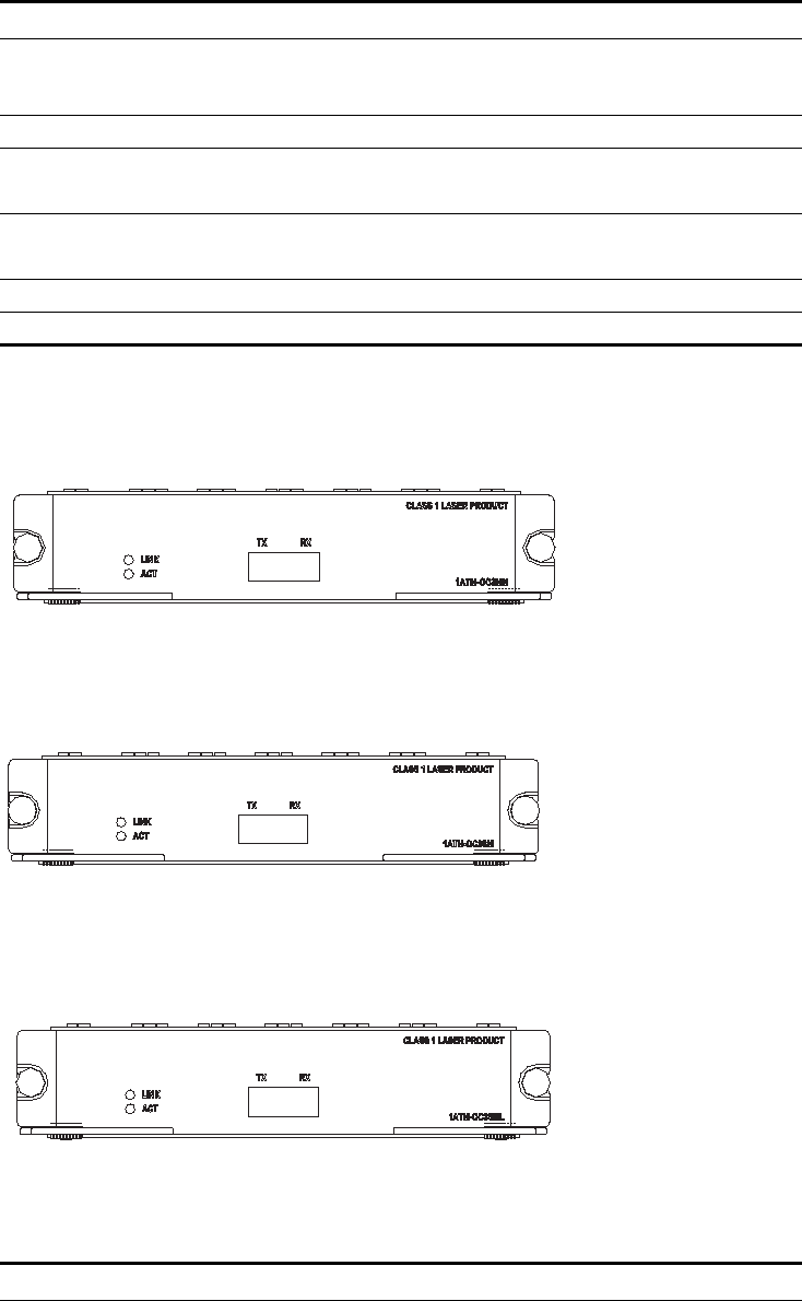
Interface LEDs The following figure illustrates the FIC-1ATM-OC3MM panel.
Figure 230 FIC-1ATM-OC3MM panel
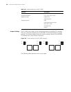
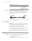
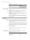
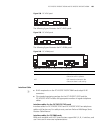
The following figure illustrates the FIC-1ATM-OC3SM panel.
Figure 231 FIC-1ATM-OC3SM panel
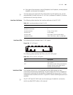
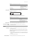
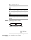
The following figure illustrates the FIC-1ATM-OC3SML panel.
Figure 232 FIC-1ATM-OC3SML panel
The following table describes the LEDs on the card panels.
Max. transmission
segment over the
selected cable
2 km (1.2 mi.) over
the multi-mode
optical fiber
15 km (9.3 mi.) over
the single-mode
optical fiber
Single-mode optical
fiber of 30km
transmission distance
Transmitter LED Laser Laser
Optical transmitter
power
Min: -21dBm
Max: -14dBm
Min: -15dBm
Max: -8dBm
Min: -5dBm
Max: 0dBm
Receiver sensitivity Min: -28 dBm
Max: -8 dBm
Min: -30 dBm
Max: -14 dBm
Min: -34 dBm
Max: -10 dBm
Central wavelength 1310 nm
Supported service ATM traffic CBR, rt_VBR, nrt_VBR, UBR
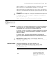
Table 133 Interface attributes of the ATM cards
Attribute FIC-1ATM-OC3MM FIC-1ATM-OC3SM FIC-1ATM-OC3SML
Table 134 LEDs on the ATM card panels
LED Description
LINK OFF means no link is present; ON
means a link is present.