


32 CHAPTER 2: SMART INTERFACE CARDS
If the SIC has been properly installed, follow these steps to connect the cable:
Step 1: Check the type of E1 cable and correctly set the DIP switch (the ex-factory
setting of E1/CE1/PRI interface impedance is 75-ohm);
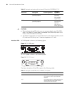
Step 2: Connect the DB-15 connector of E1 cable to SIC-1EPRI/SIC-1E1-F;
Step 3: Connect the other end of the E1 cable to the corresponding network
device:
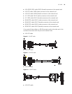
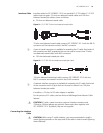
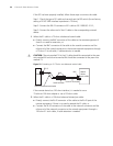
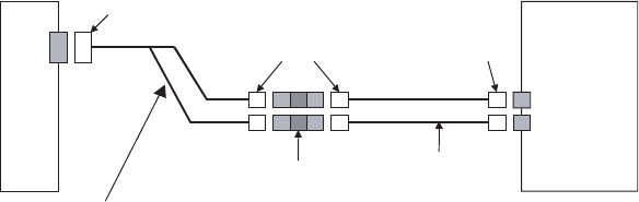
1 When the E1 cable is a 75-ohm unbalanced coaxial cable:
■ Directly connect the BNC connector of the cable to the remote equipment if
there is no need for extension, or
■ Connect the BNC connector of the cable to the coaxial connector and the
other end of the coaxial connector to the remote network equipment through
a 75-ohm E1 trunk cable, if cable extension is needed.
c
CAUTION: The wire marked TX in the E1 cable should be connected to the peer
wire marked RX and the wire marked RX should be connected to the peer wire
marked TX.
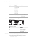
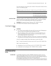
Figure 23 Extending an E1 75-ohm non-balanced coaxial cable
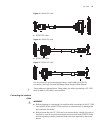
If the remote device has 120-ohm interface, it is needed to use a
75-ohm-to-120-ohm adapter or use a 120-ohm cable.
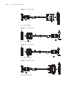
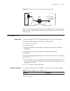
2 When the E1 cable is a 120-ohm balanced twisted pair cable:
■ Directly connect the RJ-45 connector of the cable to the RJ-45 port of the
remote equipment, if there is no need to extend the E1 cable, or
■ Connect the RJ-45 connector of the cable to the network connector and the
other end of the network connector to the network equipment through a
120-ohm E1 trunk cable, if cable extension is needed.
Router
Network
devices
such as DDN
DB-15
Coaxial connector
BNC
BNC
75-ohm non-balanced coaxial cable
75-ohm E1 trunk cable