


172 CHAPTER 4: FLEXIBLE INTERFACE CARDS
Connecting the Interface
Cable
c
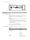
CAUTION: Before you connect a port, read its label carefully; a wrong connection
may impair the interface card and even damage the device.
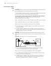
You are recommended to install a special lightning arrester at the input end of the
interface cable for better lightning protection.
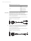
Step 1: Choose an 8E1 conversion cable appropriate to the interface type of the
device to be connected.
■ If the interface impedance of the device is 75-ohm, use a 75-ohm 8E1
conversion cable.
■ If the interface impedance of the device is 120-ohm, use a 120-ohm 8E1
conversion cable.
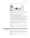
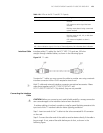
Step 2: Insert the DB-68 connector of the cable to the DB-68 port on the
FIC-8E1/FIC-8E1-F card, and fasten the cable fastening screws.
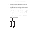
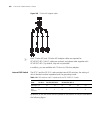
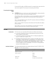
Step 3: Identify the sequence number of the other end of the 8E1/4E1 conversion
cable and connect it with a peer device.
Step 4: Power on the router. Check the behavior of the LINK LED on the card
panel: OFF means fault has occurred on the line and signal is out of
synchronization. Check the line status.
FIC-1T1/FIC-2T1/FIC-4T
1 and
FIC-1T1-F/FIC-2T1-F/FIC
-4T1-F
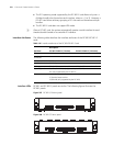
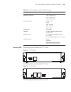
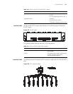
Introduction FIC-1T1/FIC-2T1/FIC-4T1
FIC-1T1/FIC-2T1/FIC-4T1, the 1-/2-/4-port channelized T1/PRI interface card,
transmits, receives, and processes T1 data traffic. In addition, you can use the card
for other purposes, such as CT1 access and the ISDN PRI function.
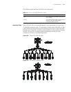
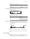
FIC-1T1-F/FIC-2T1-F/FIC-4T1-F
FIC-1T1-F/FIC-2T1-F/FIC-4T1-F, the 1-/2-4-port fractional T1 interface card, differs
from the FIC-1T1/FIC-2T1/FIC-4T1 primarily in the sense that:
■ The FT1 operating mode supported by the T1-F cards allows only one n × 64
kbps or n × 56 kbps bundle to be formed on each interface, where n = 1 to 24.
However, a T1 card allows arbitrary grouping of 24 channels and multiple
bundles.
■ The FIC-T1-F cards do not support PRI mode.
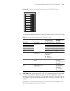
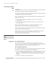
Interface Attributes The following table describes the interface attributes of the FIC-T1/FIC-T1-F cards.