


142 CHAPTER 3: MULTIFUNCTIONAL INTERFACE MODULES
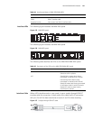
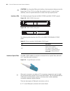
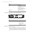
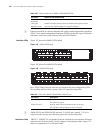
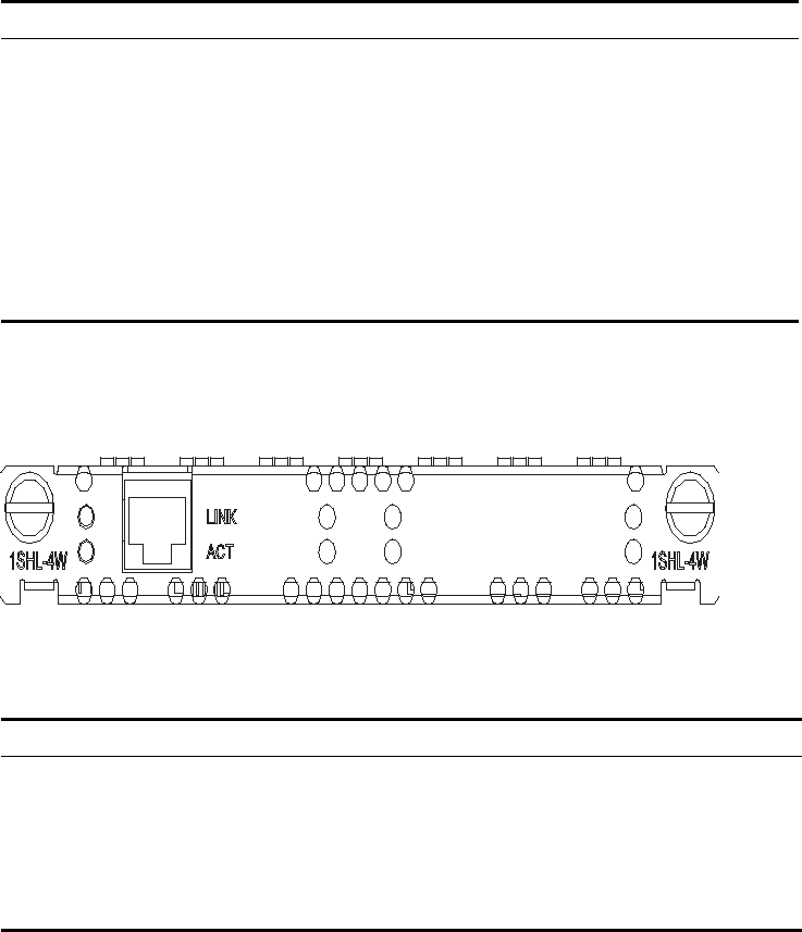
Interface LEDs The following figure illustrates the MIM-1SHL-4W panel:
Figure 162 MIM-1SHL-4W panel
The following table describes the LEDs on the MIM-1SHL-4W panel.
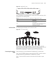
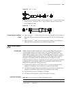
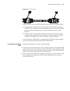
Interface Cable MIM-1SHL-4W uses a tailor-made 4-wire telephone cable of type “Y” or “I”. You
can select the type as needed.
■ As shown in the following figure, on one end of the type “Y” G.SHDSL cable
there is one RJ-11 connector (X1), which is used to connect the MIM-1SHL-4W
module; on the other end there are two RJ-11 connectors (X2 and X3), which
can connect two 2-wire telephone lines. Pins 3 and 4 of X1 are connected with
pins 3 and 4 of X2, and pins 2 and 5 of X1 are connected with pins 3 and 4 of
X3.
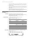
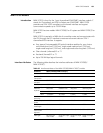
Interface rate In single-pair mode, supports the sending
and receiving independent symmetric rates
in the range from 192 kbps to 2312 kbps
in steps of 8 kbps.
In dual-pair mode, supports the
sending/receiving independent symmetric
rates in the range from 384 kbps to 4624
kbps in steps of 16 kbps.
Interface cable Tailor-made 4-wire telephone cable
Supported services G.SHDSL access over ordinary telephone
lines
Table 98 Interface attributes of the MIM-1SHL-4W
Attribute MIM-1SHL-4W
Table 99 LEDs on the MIM-1SHL-4W panel
LED Description
LINK OFF means no link is present.
ON means a link is present.
ACT OFF means no data is being
transmitted or received.
Blinking means data is being received
or transmitted.