


68 CHAPTER 3: MULTIFUNCTIONAL INTERFACE MODULES
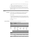
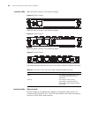
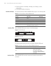
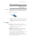
Interface LEDs MIM-1FE panel is shown in the following figure:
Figure 63 MIM-1FE panel
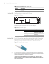
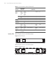
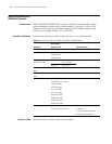
MIM-2FE panel is shown in the following figure:
Figure 64 MIM-2FE panel
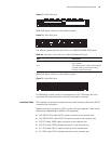
MIM-4FE panel is shown in the following figure:
Figure 65 MIM-4FE panel
The following table describes the LEDs on the MIM-1FE/MIM-2FE/MIM-4FE panel:
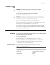
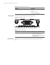
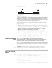
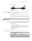
Interface Cable Ethernet cable
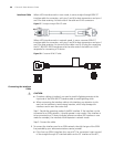
Ethernet cables for FE modules are category 5 twisted pair cables with RJ-45
connectors (see Figure 66). Pins 1 and 2 of the interface are for data transmission,
and Pins 3 and 6 are for data receiving.
Table 38 Description of the LEDs on the MIM-1FE/MIM-2FE/MIM-4FE panel
LED Description
LINK OFF means the Ethernet link is not
connected. ON means the link is
connected.
ACTIVE OFF means no data is being
transmitted or received; blinking
means data is being received or/and
transmitted.