


Ethernet+Modem/Fax PC Card User’s Guide
Using 1Step 3-3
Setting the Hardware Configuration
Select the appropriate I/O base address and interrupt for diagnostics. You can
point and click with the mouse or use the keyboard to make selections.
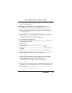
Selecting the I/O Base Address
The I/O base address is a channel through which information is transferred
between the card and the host PC. It is important to note that each peripheral
installed in the host PC should be assigned a unique I/O base address. Check the
documentation that came with your computer to determine which addresses are
already in use.
The PC Card allows I/O base address selections of 300, 320, 340 and 360. The
factory default setting is 300h.
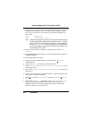
Selecting the Interrupt
The interrupt is an electronic signal from the card that goes to the host computer’s
CPU when a request is made. Each peripheral installed in the host PC is assigned
a unique interrupt channel. (The word interrupt is used interchangeably with
IRQ). A unique interrupt channel should be assigned for the Card. Check the
documentation that came with your computer to determine which interrupts are
already in use.
Make sure that a unique interrupt is assigned to the card. There are eight interrupt
selections available, namely, 3, 4, 5, 2(9), 10, 11, 12 and 15. The adapter’s default
interrupt setting is 5.
Note: You can now perform the diagnostic tests described in the next section.
However, remember that your hardware settings are only effective while
running 1Step. The original settings will be automatically restored when you
exit 1Step.