


Ethernet+Modem/Fax PC Card User’s Guide
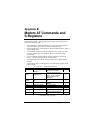
B-4 Modem AT Commands and S-Registers
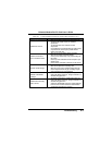
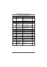
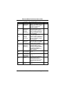
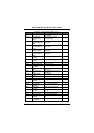
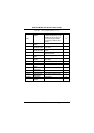
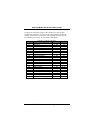
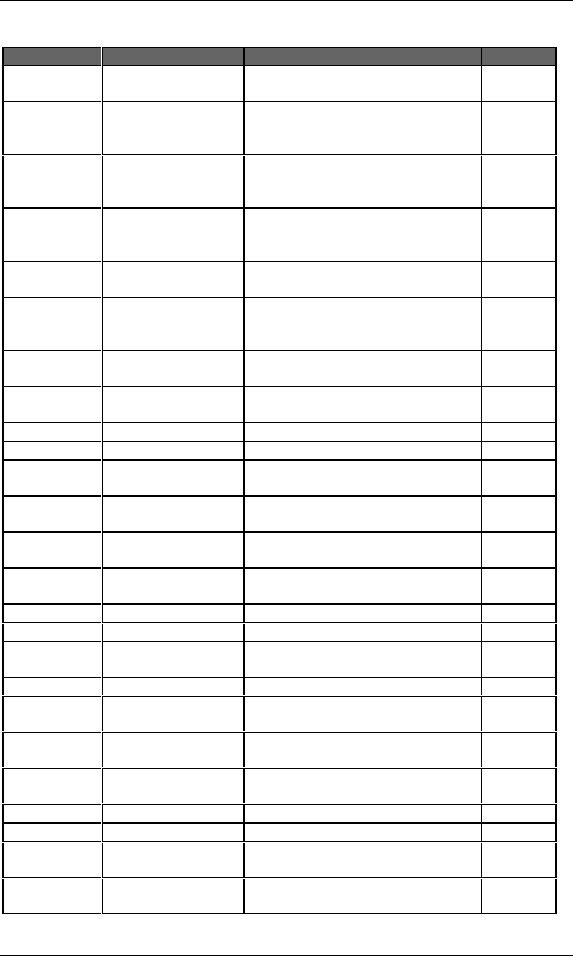
Table B.1 AT Command Summary (cont.)
Command Description Usage Default
AT&C0 Force RLSD active Force RLSD active regardless of the
carrier status
N
AT&C1 Allow RLSD to
follow the carrier
state
Normally used in reset and
initialization strings
Y
AT&D0 Interpret DTR On-
to-Off transition per
&Qn
Prepares the modem for normal
data transfer
N
AT&D1 Interpret DTR On-
to-Off transition per
&Qn
Prepares the modem for normal
data transfer
N
AT&D2 Data Terminal
Ready (selected)
Prepares the modem for normal
data transfer
Y
AT&D3 Interpret DTR On-
to-Off transition per
&Qn
Prepares the modem for normal
data transfer
Y
AT&F0 Reset to default
settings
Restore factory configuration 0. N
AT&F1 Reset to default
settings
Restore factory configuration 1. N
AT&Go Disable guard tone Disable guard tone N
AT&G1 Disable guard tone Disable guard tone N
AT&G2 Enable 1800 Hz
guard tone
Enable 1800 Hz guard tone N
AT&P0 Set 10 pps pulse
dial
Set 10 pps pulse dial with 39%/61%
make/break
Y
AT&P1 Set 10 pps pulse
dial
Set 10 pps pulse dial with 33%/67%
make/break
N
AT&S0 DSR is always
active
Activates DSR Y
AT&S1 DSR acts per V.25 DSR acts per V.25 N
AT&T0 Terminate test Terminate any test in progress Y
AT&T1 Initiate analog
loopback
Initiate local analog loopback N
AT&T2 Result code Returns ERROR result code N
AT&T3 Initiate digital
loopback
Initiate local digital loopback N
AT&T4 Allow digital
loopback
Allow remote digital loopback N
AT&T5 Disallow loopback
request
Disallow remote digital loopback
request
N
AT&T6 Request an RDL Request RDL without self-test N
AT&T7 Request an RDL Request RDL with self-test N
AT&T8 Initiate analog
loopback
Initiate local analog loop with self-
test
N
AT&V Display
configuration
Display current configuration N