


Basic Configuration
3-35
3
Setting the System Clock
Simple Network Time Protocol (SNTP) allows the switch to set its internal clock
based on periodic updates from a Network Time Protocol (NTP) server. Maintaining
an accurate time on the switch enables the system log to record meaningful dates
and times for event entries. You can also manually set the clock using the CLI. (See
“calendar set” on page 4-62.) If the clock is not set, the switch will only record the
time from the factory default set at the last bootup.
When the SNTP client is enabled, the switch periodically sends a request for a time
update to a configured time server. You can configure up to three time server IP
addresses. The switch will attempt to poll each server in the configured sequence.
For more robust, secure time updates from trusted servers, the NTP client can be
enabled instead of the SNTP client. Using the NTP client provides more reliable time
updates, since the updates are collected from many NTP servers, then filtered and
selected using an algorithm that determines the most accurate time. The NTP client
also uses authentication and encryption to ensure that updates are received from
authorized servers only.
Note:
The SNTP and NTP client cannot be enabled at the same time.
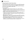
Configuring SNTP
You can configure the switch to send time synchronization requests to time servers.
Command Attributes
• SNTP Client – Configures the switch to operate as an SNTP client. This requires
at least one time server to be specified in the SNTP Server field. (Default: Disabled)
• SNTP Poll Interval – Sets the interval between sending requests for a time update
from a time server. (Range: 16-16384 seconds; Default: 16 seconds)
• SNTP Server – Sets the IP address for up to three time servers. The switch
attempts to update the time from the first server, if this fails it attempts an update
from the next server in the sequence.
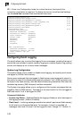
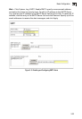
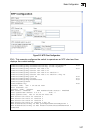
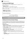
Web – Select NTP/SNTP, Configuration. Modify any of the required parameters, and
click Apply.
Figure 3-21 SNTP Configuration