45
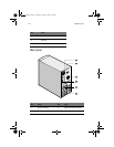
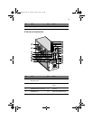
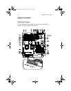
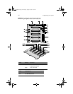
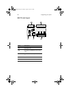
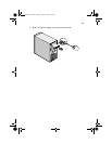
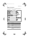
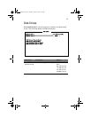
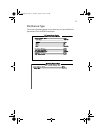
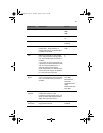
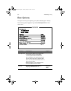
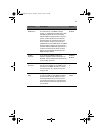
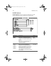
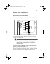
CN2 For SAF-TE card use (or for terminator
board)
CN3 SCSI 68-pin P connector - In
CN4 Front power LED connector
CN5
I
2
C buffer connector
JP1
I
2
C buffer ID setting
JP3
Power connector
a
JP4 Power connector
JP5 3-pin FAN connector
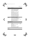
S1
Slot 1 ID switch
b
S2 Slot 2 ID switch
S3 Slot 3 ID switch
S4 Slot 4 ID switch
S5 Slot 5 ID switch
Slot1 SCSI slot 1 connector
Slot2 SCSI slot 2connector
Slot3 SCSI slot 3 connector
Slot4 SCSI slot 4 connector
Slot5 SCSI slot 5 connector
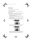
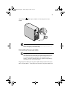
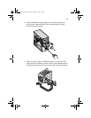
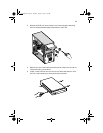
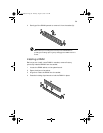
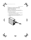
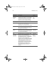
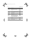
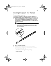
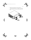
a. For the SCSI backplane board's loading requirement, please insert an inde-
pendent power cable to each power connector on the backplane board.
The power cable should not connect to any other device.
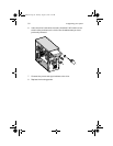
b. When you use the LVD SCSI hot-swap cage to arrange your system hard
drives, please remove all the jumpers on each SCSI hard drive and use the
switches on the backplane board (S1~S5) to set the hard drive's ID.
Label Description
AA G600.book Page 45 Thursday, August 23, 2001 2:31 PM