MX410/MX412 System Manual Drop and Insert Application
61189500L1-1B PRELIMINARY 3-7
Drop and Insert Application
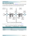
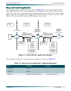
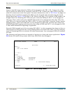
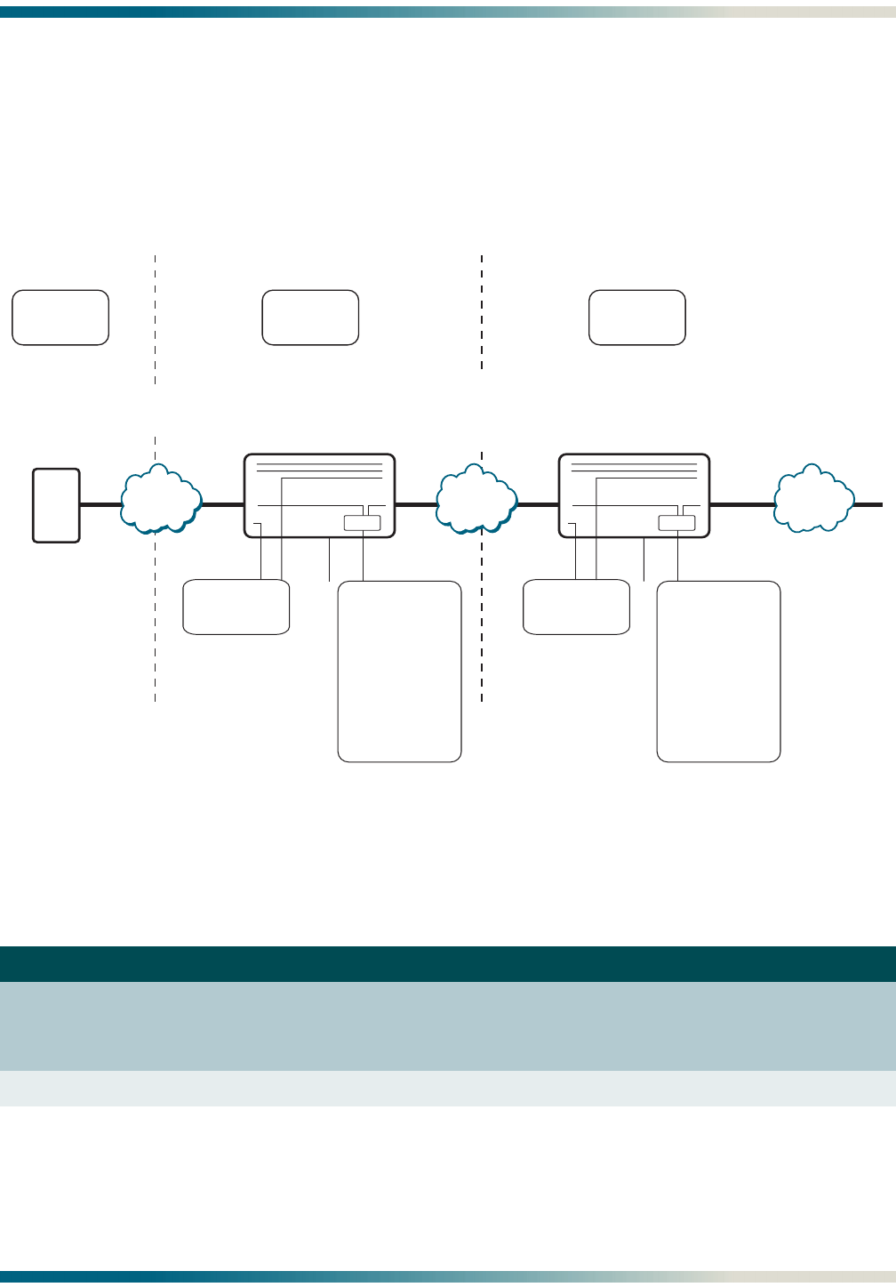
The following applies to Remote Site #1 shown in Figure 3-7. In the Drop and Insert Appli-
cation DS0s from one DS1 can be dropped out to the other DS1 ports. Then, DS0s from the
other DS1 ports can be inserted into the corresponding DS0s in the other DS1. In the example
shown, any DS0 not dropped will be mapped to continue on from one DS1 to another. This
allows a DS1 to be used to transport DS0s between several sites.
Figure 3-7. Drop and Insert Application Diagram
The equipment needed for a Drop and Insert application is shown in Table 3-2.
Table 3-2. Drop and Insert Application - Required Equipment
Part # Equipment Quantity
1189500L1
or
1189512L1
MX410
MX412
1
1
1189501L1 MX410 PSU (MX410 only) 1 (2 for redundancy)
DS1
µ Wave/
Leased
DS1
DS1
µ Wave/
Leased
DS1
DS1
µ Wave/
Leased
DS1
V.35
MX410
DS1
DS1
ETH1
Switch
V.35
MX410
DS1
DS1
ETH1
Switch
24 DS0s
from Central Site
Original DS0s
Continue
Downstream;
All Ones in
Unmapped DS0s
Original DS0s
Continue
Downstream;
All Ones in
Unmapped DS0s
DS1 DS1 DS1DS1 DS1
Remote
Site #2
Remote
Site #1
Central
Site
DS0s
to/from Local
Equipment
DS0s
to/from Local
Equipment
Drop DS0s
to PPP to
Control
Local
Equipment
via Ethernet
Insert DS0s
from
PPP to Continue
Ethernet Path
Conserving
Bandwidth
Drop DS0s
to PPP to
Control
Local
Equipment
via Ethernet
Insert DS0s
from
PPP to Continue
Ethernet Path
Conserving
Bandwidth


