


Turn-up MX410/MX412 System Manual
4-12 PRELIMINARY 61189500L1-1B
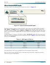
3. Install the power connector for DC power feeds A and B by connecting RET A, PWR A, RET
B
, and PWR B to the power connector. PWR refers to respective –48 VDC or ±24 VDC power
sources, while
RET refers to respective returns.
a. Insert the power wires into the power connector and tighten the hold-down screws on
the top of the power connector.
b. Insert the power connector into the MX410/MX412 and tighten the two screws on the
front of the power connector.
4. Install at least one PSU into the MX410 front panel
PSU A or PSU B slot.
a. Line up the PSU with the guide grooves and carefully insert the unit into the MX410
until it seats all the way into the PSU slot of the MX410.
b. Tighten the thumb screws to secure the PSU in place.
To remove a PSU, remove the thumb screws that hold the PSU in place and carefully pull the
PSU straight out of the MX410.
Refer to “LED Indicators” on page 4-10 for LED indication of successful power turn-up.