


Getting Started 1
U2761A User’s Guide 23
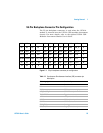
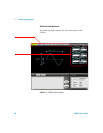
55-Pin Backplane Connector Pin Configuration
The 55-pin backplane connector is used when the U2761A
module is inserted into the U2781A USB modular instrument
chassis. For more details, refer to the Agilent U2781A USB
Modular Instrument Chassis User's Guide.
Figure 1-1 55-pin backplane connector pin configuration
GND
NC
GND
TRIG4
nBPUB
NC
11
GND
NC
TRIG3
GND
CLK10M
NC
10
GND
NC
GND
TRIG5
GND
NC
9
GND
NC
STAR_TRIG
NC
8
TRIG2
GND
GND
NC
GND
TRIG6
GA2
NC
7
GND
NC
TRIG1
GND
GA1
NC
6
GND
NC
GND
TRIG7
GA0
NC
5
GND
NC
TRIG0
GND
NC
NC
4
GND
VBUS
GND
+12 V
+12 V
+12 V
3
GND
GND
GND
+12 V
+12 V
+12 V
2
GND
USB_D
–
USB_D+
GND
+12 V
+12 V
1
F
E
D
C
B
A
Table 1-1 Synchronous Simultaneous Interface (SSI) connector pin
description
SSI timing signal Functionality
GND Ground
NC Not connected
VBUS USB bus power sensing input
USB_D+, USB_D– USB differential pair
TRIG0~TRIG7 Trigger bus
+12 V +12 V power with 4 A current
nBPUB USB backplane input detect
CLK10M 10 MHz clock source
STAR_TRIG Star trigger
GA0,GA1,GA2 Geographical address pin