


AT-iMG646xx Series Intelligent Multiservice Gateway and AT-EN646 Enclosure Installation Guide
Section I: Outdoor Installation 41
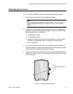
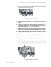
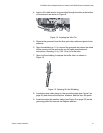
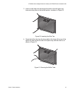
4. Insert a UV-rated wire tie (not provided) through the slots at the bottom
of the entrance as shown in Figure 8.
Figure 14. Inserting the Wire Tie
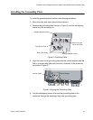
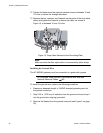
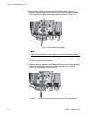
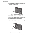
5. Remove the grommet from the fiber optic drop cable and ground wire
entrance.
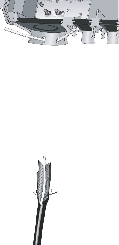
6. Open the shielding to 1.5 in. beyond the grommet slot where the cable
will be coming into the enclosure, per the cable manufacturer’s
instructions, exposing 41 in. (104.14 cm) of buffer tube.
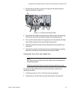
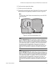
7. Open out the shielding to expose the buffer tube, as shown in
Figure 15.
Figure 15. Opening Out the Shielding
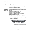
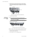
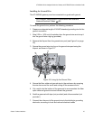
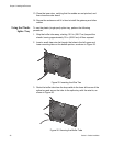
8. Locate the drop cable clamp on the grounding plate (see Figure 5 on
page 35) and remove the Kepnuts, washers, and bar from the posts.
9. Locate the strength member clamp (see Figure 5 on page 35) on the
grounding plate and remove the Kepnuts and bar.
844
1188