


Chapter 4: Installing the Gateway Outdoors
58 Section I: Outdoor Installation
Preparing and
Connecting the
Power Cord
The AT-iMG646xx series gateways are designed to be deployed with an
uninterruptible power supply (UPS). You can purchase a UPS from Allied
Telesis (part number AT-iMG005G). Install the power supply according to
the manufacturer’s instructions included in the package.
Allied Telesis provides a 15 ft. power cord (part number AT-RG013).
Alternatively, you can make custom length power cord. The terminal
adapters are supplied with the AT-iMG005G UPS and the gateways. For
lengths up to 50 ft., use three pair twisted wire with a minimum 18 AWG.
Figure 57 on page 90 provides a detailed wiring diagram.
Caution
To properly ground the unit, you MUST install a terminal block
ground wire as described in this procedure. The materials needed
for the terminal block ground wire are described in “Additional
Supplies” on page 54.
To prepare and connect the power cord, perform the following procedure:
Warning
Ensure that the UPS is OFF before you perform this procedure.
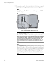
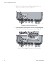
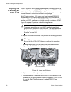
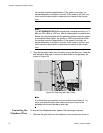
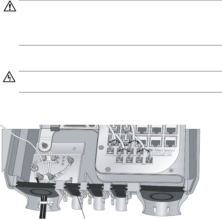
1. Remove the grommet from the power cord entrance as shown in
Figure 34, cut a 1/4” “X” in it, and put it back in place.
Figure 34. Power Cord Entrance
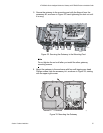
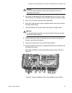
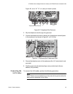
2. Slip the power cord through the grommet.
3. Connect the wires in the power cord to the DC terminal block in the
accessory kit (the wiring diagram is shown in Appendix A) at 4.5 in-lbs.
Or, use the Allied Telesis power cord, model AT-RG013 (not
provided).
857
Power Cord Entrance