


Chapter 5: Installing the Gateway Indoors
78 Section II: Indoor Installation
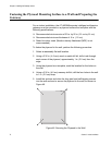
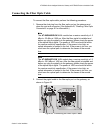
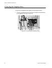
Preparing and Connecting the Power Cord
The AT-iMG646xx series intelligent multiservice gateway are designed to
be deployed with an uninterruptible power supply (UPS). You can
purchase a UPS from Allied Telesis (part number AT-iMG005G). Install
the power supply according to the manufacturer’s instructions included in
the package.
Allied Telesis provides a 15 ft. power cord (part number AT-RG013).
Alternatively, you can make custom length power cord. The terminal
adapters are supplied with the AT-iMG005G UPS and the gateways. For
lengths up to 50 ft., use three pair twisted wire with a minimum 18 AWG.
Figure 57 on page 90 provides a detailed wiring diagram.
Caution
To properly ground the unit, you MUST install a terminal block
ground wire as described in this procedure. The materials needed
for the terminal block ground wire are described in “Additional
Supplies” on page 72.
To prepare and connect the power cord, perform the following procedure:
Warning
Ensure that the UPS is OFF before you perform this procedure.
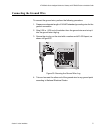
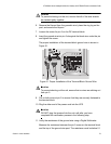
1. Connect the wires in the power cord to the DC terminal block in the
accessory kit (the wiring diagram is shown in Appendix A) at 4.5 in-lbs.
Or, use the Allied Telesis power cord, model AT-RG013 (not
provided).
Caution
To prevent electrical shock, ensure that the power cord is not
connected to the UPS.
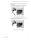
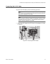
2. Cut a piece of insulated #18 AWG stranded wire to 4-1/2 to 5 in. (114.3
- 127 mm) long. The insulation color should be green with yellow
stripes.
3. Strip 1/4 in. (6 mm) of insulation from both ends.
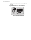
4. Slide a #10 ring lug with a green insulation jacket onto one end of the
wire and double crimp.
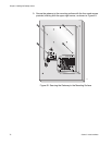
5. Twist the strands on the other end of the wire into a tight bundle.