


AT-iMG646xx Series Intelligent Multiservice Gateway and AT-EN646 Enclosure Installation Guide
Section II: Indoor Installation 79
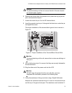
Caution
To prevent shorting out the unit, ensure that all of the wire strands
are twisted tightly together.
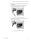
6. Remove the Kepnut from the groundin stud, place the ring lug on the
post, and secure the Kepnut.
7. Loosen the screw for pin 5 on the DC terminal block.
8. Insert the ground wire into pin 5 alongside the black wire under the pin
and tighten the screw.
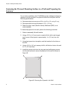
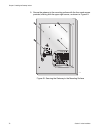
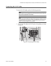
The proper installation of the terminal block ground wire is shown in
Figure 51.
Figure 51. Proper Installation of the Terminal Block Ground Wire
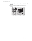
Caution
To prevent shorting out the unit, ensure that no wires are sticking out
from pin 5.
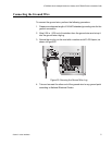
9. Pull on both wires at pin 5 to ensure that they are securely fastened to
the terminal block.
10. Plug the other end of the power cord into the UPS.
Caution
DO NOT plug the terminal into the unit until after you have
completed the verification process in the following step.
11. Verify the resistance of the ground wire using a Digital Multimeter.
Measure the resistance between the pin 5 screw on the terminal block
and the top of the ground wire post. The resistance must be below 0.1
1305