


Chapter 3: Installing the Enclosure
44 Section I: Outdoor Installation
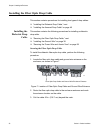
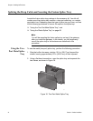
Splicing the Drop Cable and Securing the Fusion Splice Tray
Locate the fusion splice tray package in the accessory kit. Your kit will
contain one of two splice tray versions: a two-part metal tray, or a single-
part plastic tray. Depending upon the type of splice tray you have, use one
of the following procedures to secure the splice in the splice tray:
“Using the Two-Part Metal Splice Tray,” next
“Using the Plastic Splice Tray” on page 48
Note
You will be mounting the fusion splice tray on top of the gateway
after you install the gateway. In the interim, you will temporarily
mount the splice tray to the enclosure as described in this
procedure.
Using the Two-
Part Metal Splice
Tray
To use the metal (two-part) splice tray, perform the following procedure:
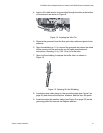
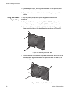
1. Strip the buffer tube away, starting 10.5 in. (26.67 cm) beyond the
sheath, leaving approximately 33 in. (83.82 cm) of fiber exposed.
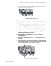
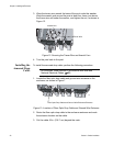
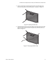
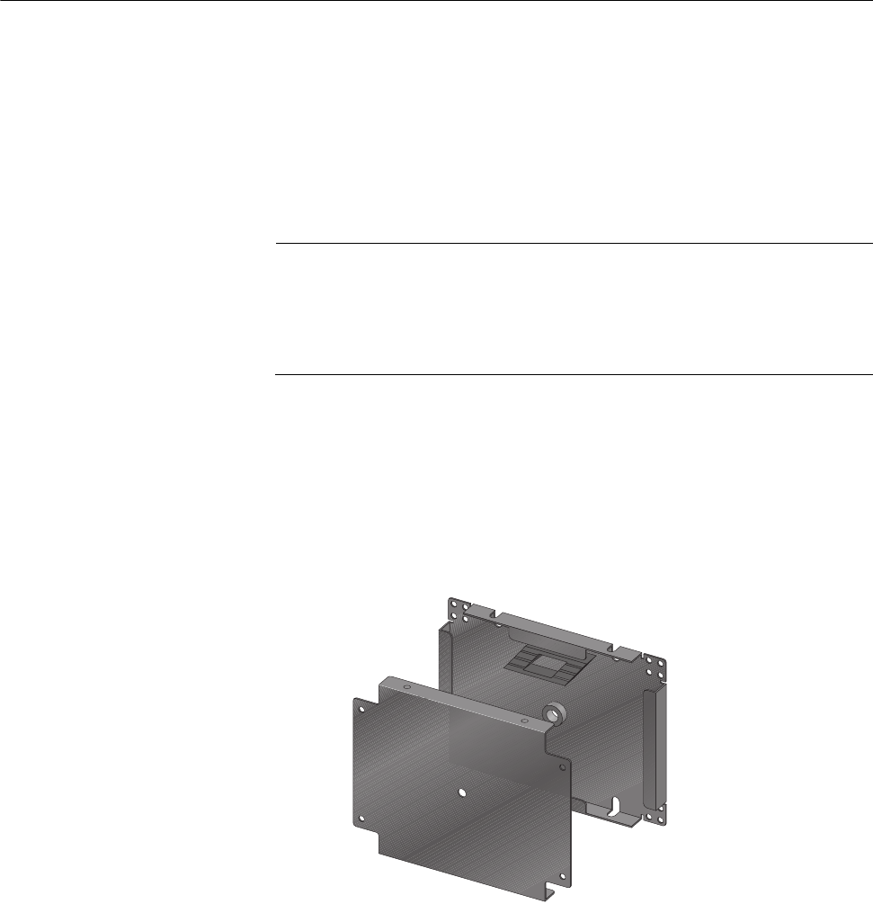
2. Using a flat-head screwdriver, open the splice tray and separate the
two halves, as shown in Figure 19.
Figure 19. Two-Part Metal Splice Tray
849