


Chapter 4: Installing the Gateway Outdoors
60 Section I: Outdoor Installation
Caution
To prevent shorting out the unit, ensure that no wires are sticking out
from pin 5.
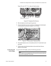
11. Pull on both wires at pin 5 to ensure that they are securely fastened to
the terminal block.
12. Plug the other end of the power cord into the UPS.
Caution
DO NOT plug the terminal into the unit until after you have
completed the verification process in the following step.
13. Verify the resistance of the ground wire using a Digital Multimeter.
Measure the resistance between the pin 5 screw on the terminal block
and the top of the ground wire post. The resistance must be below 0.1
ohm. If it is not, disconnect the power cable, repeat steps 8 through 11,
and re-test.
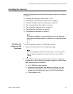
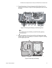
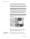
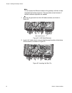
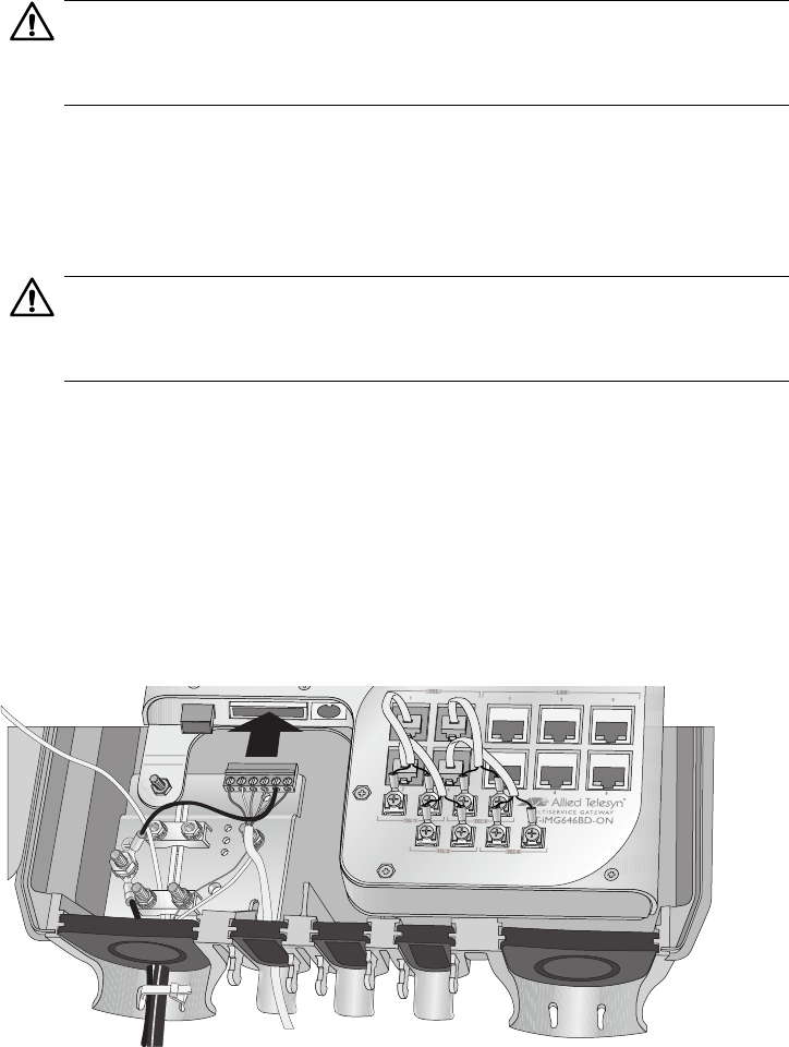
14. Plug the terminal block into the DC power socket, as shown in
Figure 36.
Figure 36. Plugging in the DC Terminal Block
15. Seal the grommet with silicone sealant.
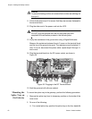
Mounting the
Splice Tray on
the Gateway
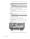
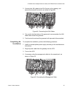
To mount the splice tray to the gateway, perform the following procedure:
1. Remove the splice tray from its temporary position on the inside of the
inner cover.
2. Do one of the following:
For a metal splice tray, position the splice tray on the four standoffs
859