


AT-iMG646xx Series Intelligent Multiservice Gateway and AT-EN646 Enclosure Installation Guide
Section II: Indoor Installation 81
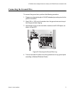
Connecting the Fiber Optic Cable
To connect the fiber optic cable, perform the following procedure:
1. Remove the dust plug from the fiber optic port on the gateway and
clean the port and connector. (See Appendix B, “Cleaning Fiber Optic
Connectors” on page 91 for information.)
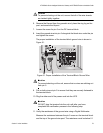
Note
The AT-iMG646BD-ON WAN module has a receive sensitivity of -3
dBm to -32 dBm at 1550 nm. After the fiber pigtail is installed and
before you plug the pigtail into the gateway, please check the power
of the optical input signal. The power at 1550 nm should fall within
the receive sensitivity specification. If the power is too high, an
optical attenuator is needed in the link. If the power is too low, you
must trace the optical path to determine the cause of the excess
loss.
Note
The AT-iMG646PX-ON WAN module has a receive sensitivity of -3
dBm to -26.5 dBm at 1490 nm. After the fiber pigtail is installed and
before you plug the pigtail into the gateway, please check the power
of the optical input signal. The power at 1490 nm should fall within
the receive sensitivity specification. If the power is too high, an
optical attenuator is needed in the link. If the power is too low, you
must trace the optical path to determine the cause of the excess
loss.
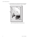
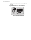
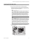
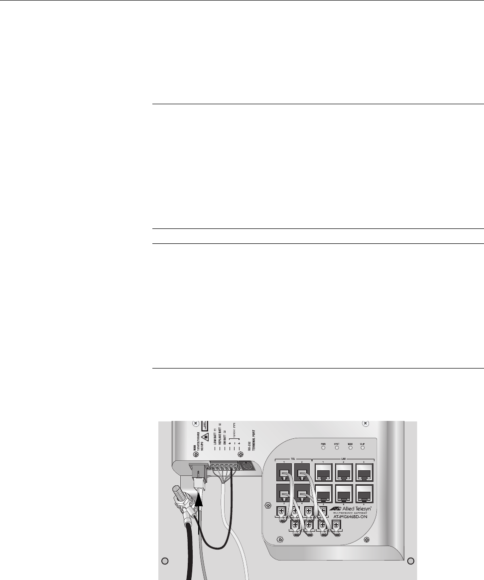
2. Connect the pigtail cable to the fiber optic port on the gateway, as
shown in Figure 53.
Figure 53. Connecting the Fiber Optic Cable
1176