


AT-iMG646xx Series Intelligent Multiservice Gateway and AT-EN646 Enclosure Installation Guide
Section I: Outdoor Installation 59
Caution
To prevent electrical shock, ensure that the power cord is not
connected to the UPS.
4. Cut a piece of insulated #18 AWG stranded wire to 5-1/2 to 6 in. (140 -
150 mm) long. The insulation color should be green with yellow stripes.
5. Strip 1/4 in. (6 mm) of insulation from both ends.
6. Slide a #10 ring lug with a green insulation jacket onto one end of the
wire and double crimp.
7. Twist the strands on the other end of the wire into a tight bundle.
Caution
To prevent shorting out the unit, ensure that all of the wire strands
are twisted tightly together.
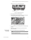
8. Remove the Kepnut from the ground wire post, place the ring lug on
the post, and secure the Kepnut.
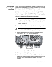
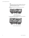
9. Loosen the screw for pin 5 on the DC terminal block.
10. Insert the ground wire into pin 5 alongside the black wire under the pin
and tighten the screw.
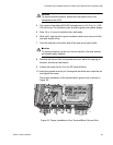
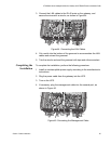
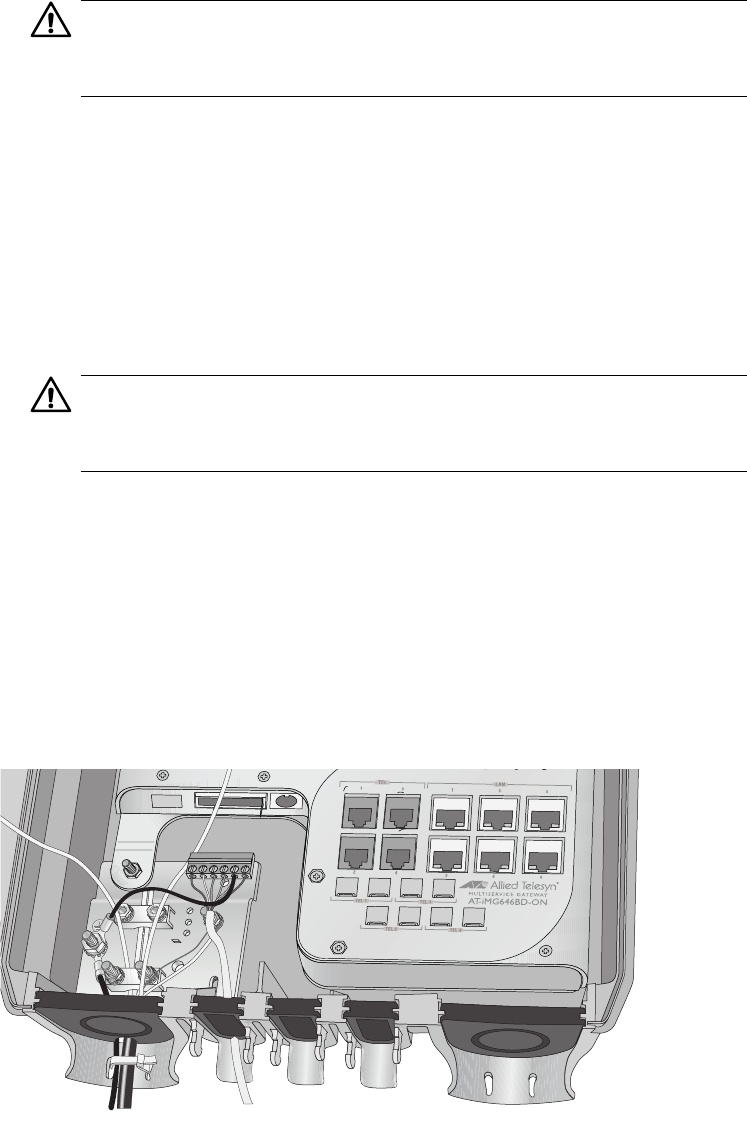
The proper installation of the terminal block ground wire is shown in
Figure 35.
Figure 35. Proper Installation of the Terminal Block Ground Wire
1304