


AT-iMG646xx Series Intelligent Multiservice Gateway and AT-EN646 Enclosure Installation Guide
Section I: Outdoor Installation 49
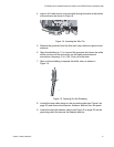
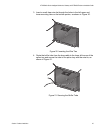
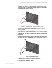
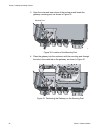
4. Route the fiber cable 2-1/2 times around the splice tray to the splice
organizer and cut it to a length that will allow the splice to be placed in
the organizer, as shown in Figure 27.
Figure 27. Setting the Fiber Cable in the Splice Tray
5. Cut the SC/UPC pigtail cable (not provided) 29.25 in. (74.30 cm)
beyond the boot.
6. Strip the SC/UPC pigtail jacket to expose 13.75 in. (39.93 cm) of fiber.
7. Clean the fiber, and splice it to the pigtail, per the splice manufacturer’s
instructions.
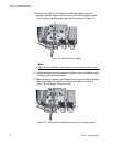
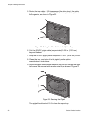
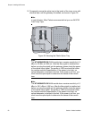
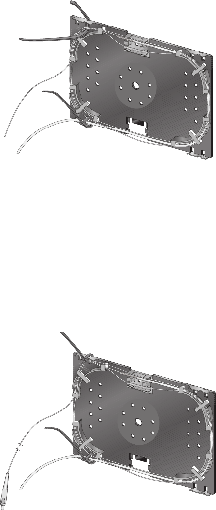
8. Route the pigtail once around the splice tray and out through the upper
left corner and secure it with another wire tie, as shown in Figure 28.
Figure 28. Securing the Pigtail
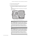
The pigtail should extend 15.5 in. from the splice tray.
9. Trim the wire ties close to the cables.
1182
1183