


Stack Installation Guide for AT-2552XS L2 Data Center Switch
17
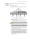
Installation Options
The AT-DC2552XS L2 Data Center Switch is designed to be installed in
one of two ways:
On a desktop.
In a 19-inch equipment rack.
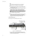
Power Supply/Fan Modules
The AT-DC2552XS must have two fan modules and at least one power
supply module installed. You may elect to install a second power supply
module for redundancy. The power supply and fan modules are:
AT-PWR06 power supply module
AT-FAN06 fan module
Note
The AT-DC2552XS must have two fan modules and at least one
power supply module installed before you power the unit on. You
may elect to install a second power supply module for redundancy.
Note
The AT-PWR06 power supply module and AT-FAN06 fan module
are sold separately from the AT-DC2552XS L2 Data Center Switch.
Contact your local Allied Telesis representative for more information.
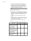
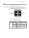
Optional SFP+ Transceivers
The following SFP+ transceivers and direct attach cable assemblies have
been approved by Allied Telesis and may be installed in the
AT-DC2552XS chassis:
Note
The SFP+ transceivers and direct attach cable assemblies are sold
separately from the AT-DC2552XS L2 Data Center Switch. Contact
your local Allied Telesis representative for more information.
SFP + modules
- AT-SP10SR (10GBASE-SR LC Ren (2))
- AT-SP10LR (10GBASE-LR LC Ren (2))
- AT-SP10TW1 (SFP + Direct Attach Cable (1m))
- AT-SP10TW3 (SFP + Direct Attach Cable (3m))
- AT-SP10TW7 (SFP + Direct Attach Cable (7m))