


Chapter 1: Overview
30
AT-PWR06 Power Supply Module
The AT-DC2552XS L2 Data Center Switch is powered by one AT-PWR06
power supply module. A second AT-PWR06 power supply module may be
installed for redundancy. The power supply module has an AC connector
on the power supply module panel and is installed by the user in slot PS1
or slot PS2. The location of these slots is shown in Figure 2 on page 20.
When two power supplies are installed and operating, only one power
supply is active at a time. The second power supply operates in a
redundant state and is automatically activated by the switch if the active
power supply loses power or fails. The change over is instantaneous and
has no effect on the Ethernet data being passed through the chassis.
Warning
Power cord is used as a disconnection device. To de-energize
equipment, disconnect the power cord. E3
Warning
This unit might have more than one power cord. To reduce the risk
of electric shock, disconnect all power cords before servicing the
unit. E30
Refer to “Power Specifications” on page 80 for the input power
specifications.
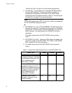
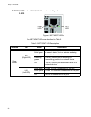
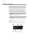
A view of the AT-PWR06 power supply module is shown in Figure 9.
Figure 9. AT-PWR06 Power Supply Module
Captive Intake
Handle
Power
Connector
AC Power
LED
Screws
Air Vents