


Chapter 3: Installing the Switch and Modules
48
Installing and Replacing AT-PWR06 Power Supply Module
The AT-PWR06 power supply module may be installed in one of the two
power supply slots - PSU1 and PSU2. See Figure 1 on page 19 for the
location of these slots.
The AT-DC2552XS L2 Data Center Switch can operate under full load
with one power supply module installed. However, if you want power
supply redundancy, a second power supply may be installed.
There is no functional difference between the two available power supply
slots. Operation of the AT-DC2552XS is the same when installed in either
slot. If you want to use only one power supply, Allied Telesis recommends
that you install it in the PSU1 slot.
The following procedures are included in this section:
“Installing Power Supply Module” on page 48
“Replacing Power Supply Module” on page 50
“Installing Power Supply Blank Cover” on page 51
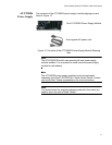
Installing Power
Supply Module
Install the AT-PWR06 power supply module by performing the following
procedure:
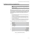
1. Identify the power supply slot where you are installing the AT-PWR06
power supply module.
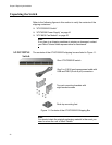
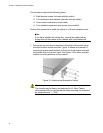
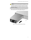
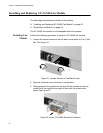
2. Loosen the captive screw on the blank cover panel of the power
supply slot blank cover and remove the cover. See Figure 18.
Figure 18. Loosen Power Supply Captive Screws
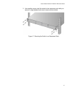
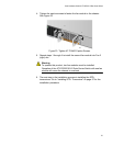
3. Store the blank cover in a safe place for future use.