


Stack Installation Guide for AT-2552XS L2 Data Center Switch
19
AT-DC2552XS
Physical
Description
The AT-DC2552XS L2 Data Center Switch physical description is as
follows:
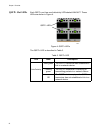
AT-DC2552XS Front Panel
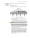
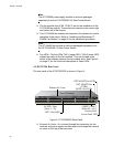
The front panel of the AT-DC2552XS is shown in Figure 1 on page 19.
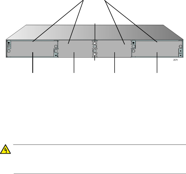
Figure 1. AT-DC2552XS Front Panel View
Blank Covers - When the switch is shipped from the factory, four
blank covers are installed.
- Two blank covers for the power supply slots (PS 1/PS 2)
- Two blank covers for the two fan module slots (FAN 1/FAN 2)
Warning
To insure proper cooling and air flow within the chassis, the blank
covers should not be removed unless an AT-PWR06 power supply
module and the AT-FAN06 fan modules are installed in their place.
The power unit slots (PS 1/PS 2) are for the installation of the
AT-PWR06 power supply module. These slots are located on the
far right and far left sides of the chassis.
A second AT-PWR06 power supply module may be installed for
redundancy, but is not required for normal operation of the switch.
With a redundant power supply configuration, you can replace one
of the two power supply modules without turning off the primary
power supply. Each AT-PWR06 power supply module that is
installed in the chassis is hot-swappable. Refer to “Installing and
Replacing AT-PWR06 Power Supply Module” on page 48 for the
installation procedure.
PS 1 FAN 1 FAN 2 PS 2
Blank
Covers
Slot Slot Slot Slot
Fan 1
LED
Fan 2
LED
[Top of Chassis]