


Chapter 1: Overview
20
Note
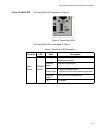
The AT-PWR06 power supply module is sold and packaged
separately from the AT-DC2552XS L2 Data Center Switch.
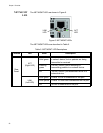
The fan module slots (FAN 1/FAN 2) are for the installation of the
AT-FAN06 fan module. These slots are located on the center right
and center left of the chassis.
Two AT-FAN06 fan modules are required in the chassis for normal
operation of the switch. Refer to “Installing and Replacing AT-
FAN06 Fan Module” on page 52 for the installation procedure.
Note
The AT-FAN06 fan module is sold and packaged separately from
the AT-DC2552XS L2 Data Center Switch.
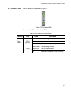
Fan LEDs - The fan LEDs FAN 1 (upper LED) / FAN 2 (lower LED)
display the status of the fan modules. They are located in the
center of the chassis between the fan module slots. See Figure 6
on page 27 for the functional description of these LEDs.
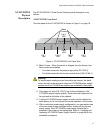
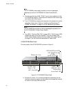
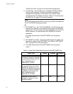
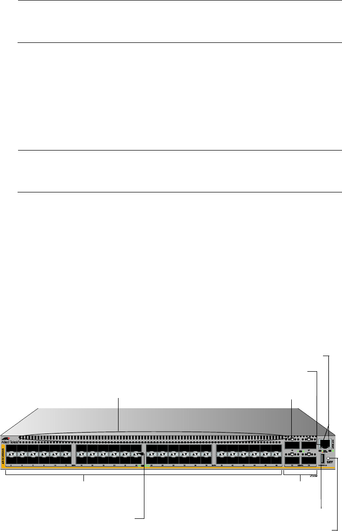
AT-DC2552XS Rear Panel
The rear panel of the AT-DC2552XS is shown in Figure 2.
Figure 2. AT-DC2552XS Rear Panel
Exhaust Air Vents - Air is forced through the chassis by the fan
modules and power supply modules and exits through the exhaust
air vents on the top of the rear panel.
NET MGMT Port LEDs
NET MGMT Port
4 QSFP+ Slots
QSFP+ Slot LEDs
Console Port
Power/Fault LED
48 SFP+ Slots
SFP+ Slot LEDs
Exhaust Air Vents
[Top of Chassis]
(Ports 1 - 48)
(Ports 49 - 64)
(ETH0)