


Stack Installation Guide for AT-2552XS L2 Data Center Switch
61
Installing QSFP+ Transceivers and Cables
Review the following guidelines before installing optional QSFP+
transceivers in the switch:
QSFP+ transceivers can be hot-swapped while the switch is
powered on. However, you should always disconnect the fiber
optic cables first before removing a module.
You should install the module before connecting the fiber optic
cable.
Unnecessary removal and insertion of a module can lead to
premature failure.
Go to “Optional QSFP+ Transceivers” on page 18 for a list of
approved QSFP+ transceivers for the AT-DC2552XS.
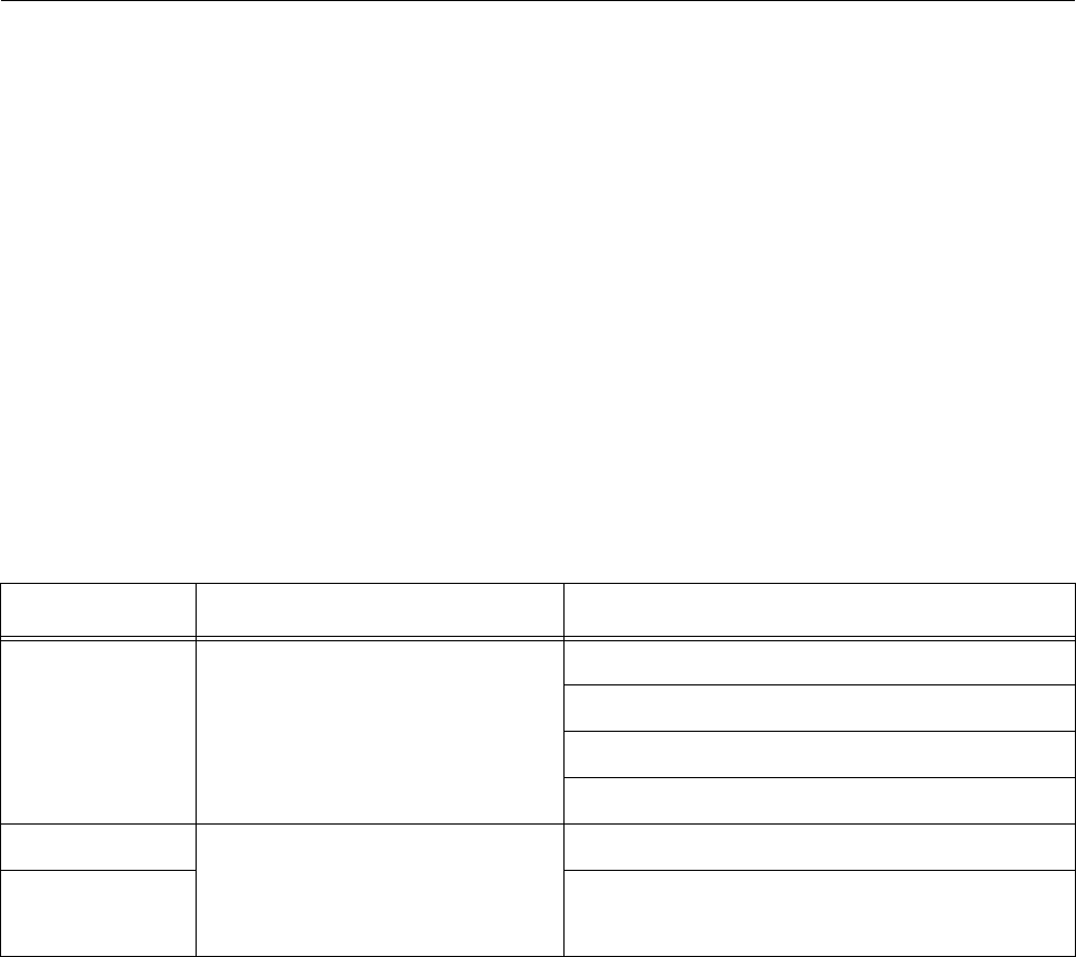
Allied Telesis recommends using the following SFP+ cables listed
in Table 10:
Installing a
QSFP+
Transceiver
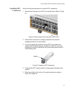
Perform the following procedure to install an QSFP+ transceiver:
1. Remove the module from its shipping container and store the
packaging material in a safe location.
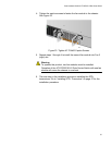
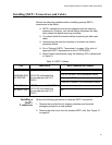
2. Remove the dust cover from the chassis QSFP+ slot. See Figure 31
on page 62.
Table 10. QSFP+ Cables
Port Cable Used Max Transmission Distance
40GBASE-SR4
AT-QSFPSR
GI 50/125 multimode fiber
(In accordance with ITU-T
G.651)
26m (At 400MHz - km transmission band)
30m (At 500MHz - km transmission band)
100m (At 2000MHz - km transmission band)
150m (At 4700MHz - km transmission band)
ET3-MTP 12-1 MTHTP cable for AT-QSFPSR
GI 50/125 multimode fiber
(In accordance with ITU-T
G.651)
1m
ET3-MTP 12-5 5m