


Chapter 2: Beginning the Installation
40
Unpacking the Switch
Refer to the following figures in this section to verify the contents of the
shipping containers:
”AT-DC2552XS Switch”
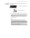
“AT-PWR06 Power Supply” on page 41
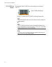
“AT-FAN06 Fan Module” on page 42
Note
If any item in a shipping container is missing or damaged, contact
your Allied Telesis sales representative for assistance.
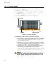
AT-DC2552XS
Switch
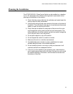
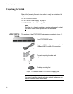
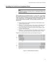
The contents of the AT-DC2552XS shipping box are listed in Figure 11.
Figure 11. Contents of the AT-DC2552XS Shipping Box
Note
You should retain the original packaging material in the event you
need to return the unit to Allied Telesis.
One AT-DC2552XS switch
Two rack mounting brackets with
eight bracket screws
Desk top mounting feet
One 2 m (6.6 ft) local management cable with
USB and DB-9 (D-sub 9-pin) connectors.