


Chapter 4: Installing the SFP+ and QSFP+ Transceivers and Cables
64
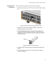
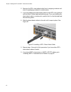
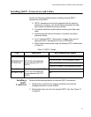
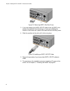
Figure 35. Removing QSFP+ Slot Dust Cover
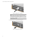
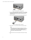
3. If you are installing the QSFP+ MTHTP cable in the top QSFP+ slot,
position the cable with the tab facing up. If you are installing the
module in the bottom slot, position the cable with the tab facing down.
4. Slide the module into the slot until it clicks into place.
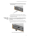
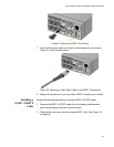
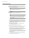
Figure 36. Installing an QSFP+ MTHTP Cable
5. Repeat this procedure if you have other QSFP+ MTHTP cables to
install.
6. The next step in the installation process is applying AC power to the
switch. Go to Chapter 5, “Powering the Switch” on page 65.