


Chapter 5: Powering the Switch
66
Powering On the Switch
The power turns on automatically when you connect the power cable to
one or both of the AT-PWR06 power supply modules. To power on the
switch, perform the following procedure:
Note
Power cord is used as a disconnection device. To de-energize
equipment, disconnect the power cord. E3
Warning
Pluggable Equipment. The socket outlet shall be installed near the
equipment and shall be easily accessible. E5
Note
If one of the power supply slots is empty with the power supply unit
not installed, install the cover panel before powering the switch on.
Refer to “Installing and Replacing AT-PWR06 Power Supply
Module” on page 48
1. Inspect the front of the AT-DC2552XS chassis to insure that at least
one AT-PWR06 power supply module and two AT-FAN06 fan modules
are installed. If one of these modules needs to be installed, perform
the steps described in “Installing Power Supply Module” on page 48 or
“Installing Fan Module” on page 52.
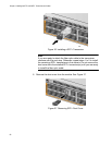
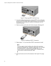
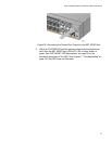
2. Connect the AC power cable to the AC power connector on the
AT-PWR06 power supply module.
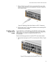
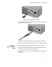
3. Connect the AC power plug to an AC power outlet.
4. With the AC power cable connected to the power supply module and
an AC power source, the AC power is turned on to the switch.
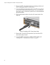
You can observe that the AT-PWR06 power (AC OK) LED is solid
green. If only one power supply module is powered on, the POWER /
FAULT LED on the back of the chassis is blinking yellow.
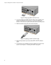
If two AT-PWR06 power supply modules are powered on, both power
supply module AC OK LEDs are solid green and the POWER / FAULT
LED is solid green too.
5. If you have installed a second redundant power supply module and
have not powered it on, repeat steps 1 - 3.