


Stack Installation Guide for AT-2552XS L2 Data Center Switch
31
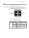
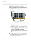
The components of the AT-PWR06 power supply module (refer to Figure 9
on page 30) are as follows:
Power connector - The AC power cable plugs into this connector.
Regional AC power cables are provided in the AT-PWR06 power
supply module shipping box. See “Powering On the Switch” on
page 66 and “Turn Off the switch” on page 68.
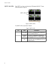
AC Power LED - This LED displays the status of the power supply
module. See “AC Power LED” on page 28 for a functional
description of this LED.
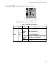
Intake Air Vents - The AT-PWR06 power supply module has two
fans which pull air into the power supply module through the intake
air vents to cool the power supply and the chassis components.
The air is discharged through the exhaust air vents on the top of
the chassis rear panel. See Figure 2 on page 20 for the location of
the exhaust vents.
Warning
On both the AT-PWR06 power supply module and AT-FAN06 fan
modules, keep the intake vents clear of any obstructions to insure
proper cooling of the switch components.
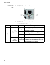
Captive screws - These two screws secure the power supply
module to the chassis frame. See “Installing and Replacing AT-
PWR06 Power Supply Module” on page 48 for the power supply
installation procedure.
Handle - The handle is used to physically push or pull the AT-
PWR06 power supply module when it is inserted or removed. See
“Installing and Replacing AT-PWR06 Power Supply Module” on
page 48 for the power supply installation procedure.