


Stack Installation Guide for AT-2552XS L2 Data Center Switch
51
Note
If a new AT-PWR06 power supply module is not available to replace
the module you are removing, perform the procedure outlined in
“Installing Power Supply Blank Cover” on page 51.
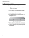
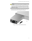
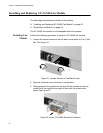
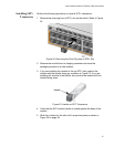
4. Slowly insert the new AT-PWR06 power supply module into the PSU
slot until it is flush with the front of the chassis.
5. Tighten the captive screws to fasten of the power supply module to the
chassis.
6. Turn the power on to the newly installed AT-PWR06 power supply
module by connecting the AC power cord.
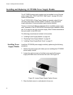
Installing Power
Supply Blank
Cover
If you have removed an AT-PWR06 power supply module from the chassis
and a replacement power supply module is not available, the blank power
supply cover should be installed to insure proper airflow in the chassis.
Caution
The PSU blank cover should be installed if an AT-PWR06 power
supply module is not installed in the power supply slot. This blank
cover assures that the correct airflow across the components within
the chassis when a power supply module is not installed.
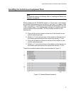
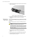
Perform the following procedure to install the blank power supply cover:
1. Locate the blank power supply cover that was originally shipped with
the chassis.
2. Remove the AT-PWR06 power supply module by following steps 1 - 3
in “Replacing Power Supply Module” on page 50.
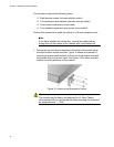
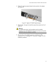
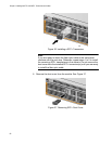
3. Once the AT-PWR06 power supply module has been removed, place
the blank power supply cover over the vacant power supply slot.
4. Tighten the captive screws on the power supply blank cover.