


44
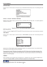
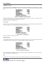
ALARM TRIGGER
Choices: 1, 2, 3, 4, 5, 6, 7, 8, 9, 10, 11, 12, 13, 14, 15, 16, 17, 18, 19, 20, 21, 22, 23,24 , 1-12, 13-24, 1-24, RTS
An Alarm Trigger is the source of activity programmed to activate a certain alarm. The alarm trigger tells the VSI-Pro
Max what exception to use to trigger the alarming device or the on-screen flag.
Choices: Exceptions 1, 2, 3, 4, 5, 6, 7, 8, 9, 10, 11, 12, 13, 14, 15, 16, 17, 18, 19, 20, 21, 22, 23, and 24 (alarms when
data is received that matches what you have set in these exception strings).
Exceptions 1-12: alarms when data is received that matches any data set in Exception 1-12.
Exceptions 13-24: alarms when data is received that matches any data set in Exception 13-24.
Exceptions 1-24: alarms when data is received that matches any data set in Exception.
RTS
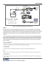
External alarm input. The VSI-Pro Max has 1 alarm input, if you are not using the handshaking function. A contact
closure to ground on pin 7 will trigger this alarm. Coupled with the RTS Triggered text, you can now display a 40
character message from an external alarm input.
1
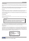
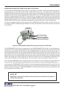
RTS APPLICATION NOTE
The RTS alarm input can be connected to the drawer of a cash register or safe to alarm and
send the message "DRAWER OPEN" to the screen if the drawer is open too long.
To select the alarm trigger that you want to program, press the “Up” or “Down” button to move the cursor to “ALARM
TRIGGER” and press “Set”. The cursor will start flashing. Press the “Up” or “Down” button to cycle through the
values and press “Set” when the desired value is displayed.
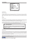
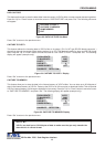
NORMAL STATE
Choices: NO (Normally open), NC (Normal closed)
There are two choices: NO (normally open) or NC (normal closed). These selections determine whether the alarm
outputs will act as a normally open switch or a normally closed switch.
To select the Normal State that you want to program, press the “Up” or “Down” button to move the cursor to “NORMAL
STATE” and press “Set”. The cursor will start flashing . Press the “Up” or “Down” button to cycle through the values
and press “Set” when the desired value is displayed.
PROGRAMMING
VSI-Pro Max POS / Cash Register Interface
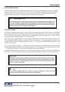
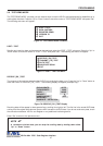
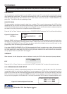
ALARM NO.
Choices: 1, 2, 3, 4, 5, 6, 7, 8, 9, 10, 11, 12, 13, 14, 15, 16
The VSI-Pro Max allows you up to 16 alarms that may be used with any of the user programmed exceptions.
However there are only 2 hardwired alarm outputs and these correspond to Alarm 1 & 2 only. The other 14 alarms
can be used to send trigger text, serial data out or flash the screen. To select the Alarm Number that you want to
program, press the “Up” or “Down” button to move the cursor to “ALARM NO.” and press “Set”. The cursor will start
flashing. Press the “Up” or “Down” button to cycle through the values and press “Set” when the desired value is
displayed.