


63
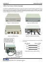
APPENDIX C DVR TEXT INPUT CONNECTIONS
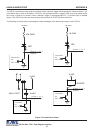
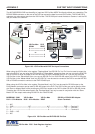
The AVE MVDR5000 DVR has the ability to input two VSI-Pro Max ASCII Text directly without any networking. The
RS-232 DB9M connector on the rear of the DVR can accept the data from one VSI-Pro Max. The RS-485 RJ12
connector can also accept data from the VSI-Pro Max. The RS-232 port inserts the data on Camera 1 and the RS-
485 port inserts on Camera 2.
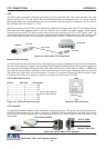
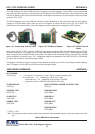
MVDR3000 / 5000 VSI-Pro Max VSI-Pro Max RS-232 to RS-422/485 Adapter
RJ12 - 6 Pin Modular RJ45 - 8 Pin Modular DB9F Screw Terminals
1 --- N/C
2 --- GND -------------------------- N/C ----------------------------- N/C ------------------------- GND ------Terminal 5
3 --- V+ ------------------------------ 4 --------------------------------- 4 ------------------------------ A+ ----- Terminal 1
4 --- V- ------------------------------- 5 --------------------------------- 6 ------------------------------ B- ------ Terminal 2
5 --- GND ---- N/C
6 --- N/C
Figure 104: VSI-Pro Max and DVR RS-485 Pin Outs
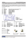
VSI-Pro Max POS / Cash Register Interface
When using the VSI-Pro Max in the register “Tapping Mode” the RS-232 Pin 3 or Pin 8 can be used to output the
text to the DVR. If you are using the VSI-Pro Max for “Slave Mode” networking then you can not use the RJ45 RS-
485 or RS-232 Pin 8 as an output to the DVR and only RS-232 is available from Pin 3. If you are not using the
VSI-Pro Max in the “Slave Mode” then you can use RS-232 Pin 8 or RJ45 RS-485 output to the DVR. If using the
VSI-Pro Max in the “Master Mode” then only RS-232 Pin 3 can be used to connect to the DVR or use the AVE RS-
232 to RS-485 converter to connect to the DVR RS-485 input.
When using the VSI-Pro Max in the register “Emulate Mode” only Pin 8 can be used for RS-232 output or the
RJ45 Network connector can be used for RS-485 output to the DVR. The VSI-Pro Max can not be used in either
the “Slave or Master Mode” while providing any ASCII text output to the DVR in either RS-232 or RS-485 format.
Therefore the VSI-Pro Max when used in the “Emulate Mode” can only be used in conjunction with the “Slave
Mode” OR Text output mode using RS-232 Pin 8 or RJ45 RS-485.
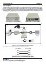
Figure 103 : VSI-Pro Max with DVR Text Input Connections
RG-59U
CAMERA
MONITOR
RS-232
RXD
RS-232
TXD
VSI-Pro Max
RG-59U
VIDEO IN
VIDEO OUT
VIDEO IN
RG-59U
VIDEO OUT
VIDEO IN
RS-485
TXD
VSI-Pro Max DVR
DB9M DB9F
3 ------------------------- 2
5 ------------------------- 5
or
8 ------------------------- 2
5 ------------------------- 5
Cash Register #2
Cash Register #1
RS-232
RXD
CAMERA