


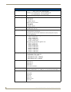

Wireless Interface Cards
17
MVP-7500/8400 Modero Viewpoint Wireless Touch Panels
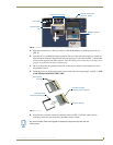
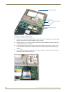
5. Grip the antenna by its sides and carefully peel-off the remaining protective film on the double-
sided tape.
6. Align the antenna into the long vertical groove in the cutout and firmly adhere it to the inner surface
of the housing. Make sure the wire is threaded along the left side of the cutout, this helps in the
removal of the cutout.
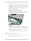
7. With the antenna now securely attached to the MVP’s inner housing, remove the cutout by carefully
pulling up on the cutout and threading the antenna wire through the
T-shaped opening.
Closing and Securing the MVP Enclosure
Once the card has been installed, close and re-secure the outer housing:
1. Reinstall the dark grey trim along the top rim of the board (A in FIG. 12).
2. While angling the top rim of the MVP’s rear outer housing (B in FIG. 12) down toward the IR
Emitters, insert the four outer housing latches into their corresponding attachment locations along
the top rim of the MVP panel (two on either side of the IR Emitters).
3. While firmly holding the top rims together, gently press down on the bottom ridge of the outer
housing (at the latch locations) and verify that each housing latch fits within its corresponding
attachment location on the board. When done, complete the insertion of the remaining housing
latches.
4. Verify that the notches along the bottom of the plastic battery slot separator strip also fit into the
three provided alignment holes on the circuit board.
5. Firmly press down around the entire rim of the outer housing to snap the cover back into place.
6. Use a grounded Phillips-head screwdriver to insert and re-secure the two housing screws removed in
Step 1.
7. Insert any available batteries back into the battery compartment.
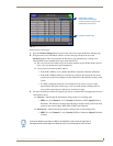
FIG. 12 Outer housing latch attachment locations
4 Outer housing latch
attachment locations
B
A
Outer housing latches (4)
Be careful not to pinch the antenna wire in the housing.