


55
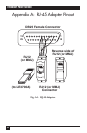
APPENDIX A: RJ-45 Adapter Pinout
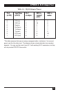
Table A-1. RJ-45 Adapter Pinout.
Pin # Signal Name Pin # DB25 to DB25 to
(at EPS) (at EPS)* at adapter terminal/ modem
printer
8 CTS (in) 1 4 5
7 DSR (in) 2 20 6
6 Receive 3 2 3
5 Rx Return 4 7 7
4 Tx Return 5 7 7
3 Transmit 6 3 2
2 DTR (out) 7 6 20
1 RTS (out) 8 5 4
*This table assumes that you are using a swapped cable, in which pin 1 at one end
goes to pin 8 at the other end. The diagram shows a terminal/printer (non-modem)
example. You can use the inner 6 pins (2-7) with existing RJ-12 connectors, but they
will not provide RTS/CTS flow control.