


57
APPENDIX C: Power-Up Tests
Appendix C: Power-Up Tests
When you power up the server, it goes through the power-up diagnostics.
These diagnostics first blink the LEDs to indicate that the processor can
execute firmware correctly and that you can individually address the LEDs.
It then tests RAM, the serial channels, and the Ethernet controller. After this,
it checksums the NVR (non-volatile RAM) to verify that the saved data,
including its Ethernet address, has not been corrupted. If the checksum test
fails, the EPS sets the Ethernet address to 00-00-00-00-00-00 (which is a known
invalid address) and resets other server parameters to factory-default values,
and calculates a new checksum.
After the EPS completes power-up diagnostics, it will attempt to boot.
If the installed Ethernet address is not valid, as in the case above, the server
will enter the boot monitor.
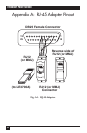
C.1 Connections and Termination
To successfully complete power-up diagnostics, you must have a valid network
connection. If you are using the AUI port, you must connect it to a properly
terminated transceiver or an AUI cable connected to a thickwire tap.. If
you are using 10BASE-T, you must connect the port to a 10BASE-T hub or
another host. A faulty transceiver or improperly terminated Ethernet may
interfere with the server’s power-up diagnostics. At power-up time, the server
does not care if there are any devices connected to the serial or parallel ports;
however, if it detects errors, it will attempt to report the problem to a device
connected to the serial port.
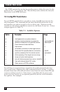
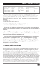
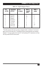
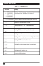
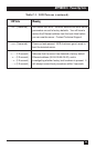
C.2 LED Patterns
As power-up tests progress, the EPS will output testing status to the LEDs in
the following sequence (although they may change too quickly to observer
when the tests pass). If a pattern is continuous, then the diagnostics have
detected an error during that test. When the EPS detects an error, it writes
the error code to the LEDs and then attempts to write a failure message out
of port 1 at 9600 baud, 8 bits, no parity, to notify the user. Depending on the
nature of the error, this may not be possible. In each of the situations
described below, the four LEDs are shown in Table C-1 as being on (•) or
off (-).