2
Bosch Security Systems | 04-2003 | 3922 988 43318 en
Digital Congress Network | Installation and Operating Manual | Chapter 8 - Information Displays
en | 8-4
LBB 3512/00 Data Distribution Board
8.1.2 Installing Data Distribution board LBB 3512/00.
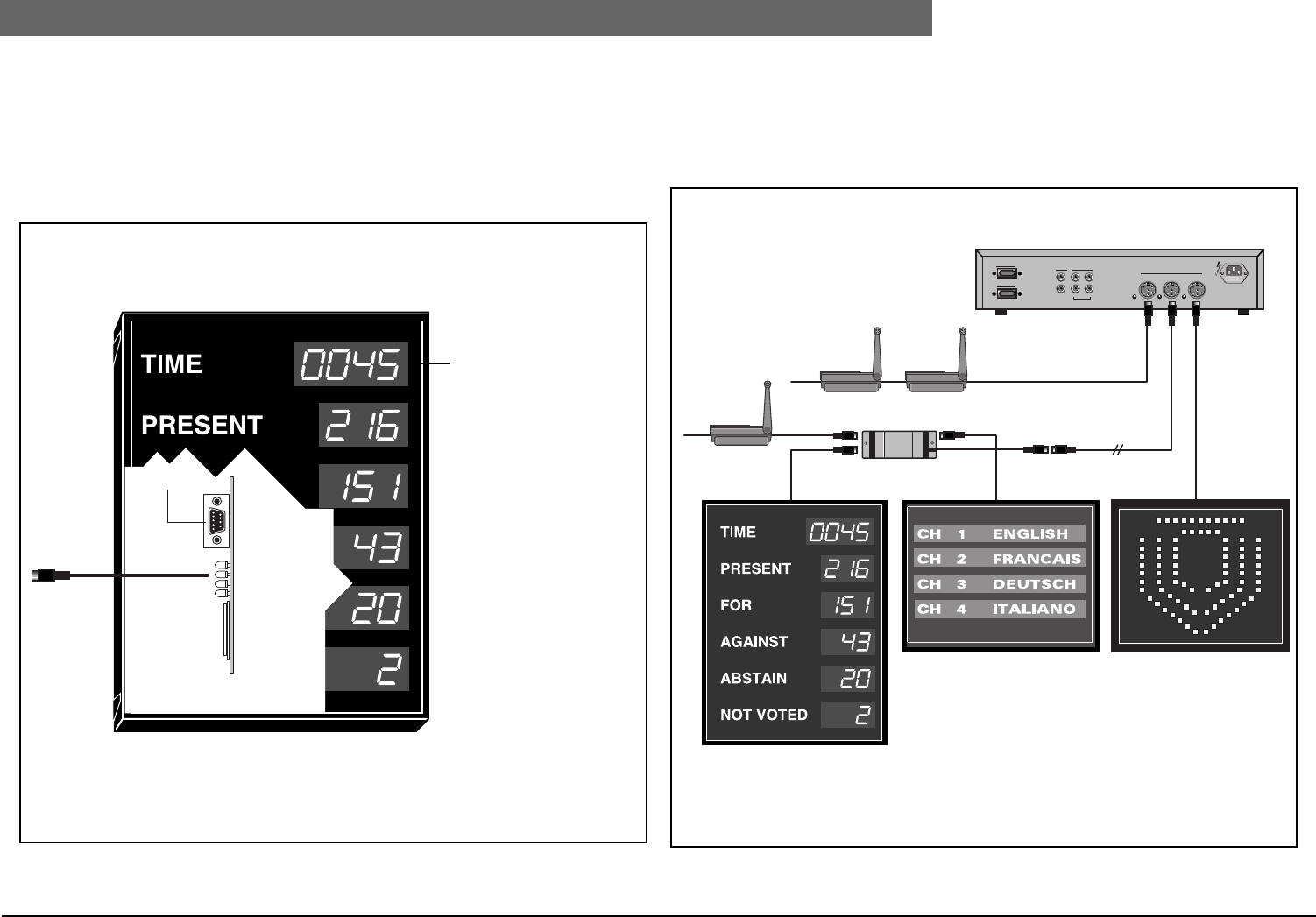
To install the board, first mount and secure the board in a convenient position inside the relevant hall
display. Connect one end of the connector cable to the 9-pole Sub-D connector on the data
distribution board and connect the other end to the displays RS232 port. The length of cable should
not exceed 5 m (16.4 ft.) when using a baud rate of 9600. The boards 2m (6.5 ft.) long cable,
terminated with a 6-pole connector, connects directly to the DCN system trunk-line. To extend the
length of cable to the trunk-line, extension cables LBB 4116/.. can be used.
FIG 8-7 Installing Data Distribution Board LBB 3512/00
8.1.3 Connecting Hall Displays to the DCN System
FIG 8-8 shows a typical example using a trunk-splitter when connecting hall displays to the DCN
system. When placing displays in the far off corners of a large conference room, extension cables
LBB 4116/.. can be used. See Chapter 8.1: “LBB 3512/00 Data Distribution Board” for the address
allocation and board settings of the LBB 3512/00.
FIG 8-8 Typical layout for connecting hall display
RS 232
LBB 3512/00
NOTE: The displayed time
is derived from a ‘built-in’
clock, and NOT from the
DCN system itself.
To DCN
system
Numeric Display fitted with
Data Distribution Board
LBB 3512/00
Address 248
Alphanumeric Display* fitted
with Data Distribution Board
LBB 3512/00
Address 249-250
Geographical Status Display*
fitted with Data Distribution
Board LBB 3512/00
Address 251
LBB 3500/..
Port 1
Port 2
Rec.
Line
In
Out
In
Out
Symmetrical
Trunk
115V-T4A 230V -T2A
*Running only with software-modules on Control-PC


