2
Bosch Security Systems | 04-2003 | 3922 988 43318 en
Digital Congress Network | Installation and Operating Manual | Chapter 11 - System Set-up and Operation
en | 11-19
Operating the Interpreter Desk
11.10.7 Typical Displays showing outgoing channels
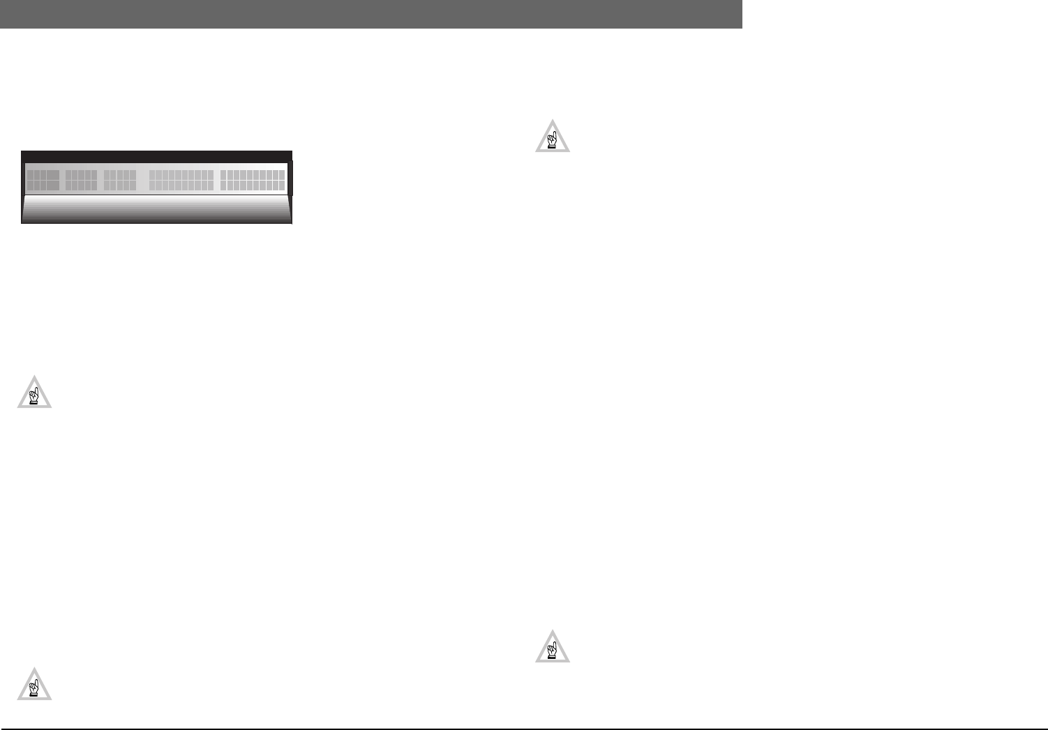
The following display shows the interpreter desk displaying both the incoming language channels and
the outgoing language channels The incoming languages are displayed in their abbreviated form along
with their channel number, and the outgoing channels are displayed in full with the channel number
displayed above.
Engaged LEDs
The A and B outgoing channel engaged LEDs, indicate when the relevant channels are occupied. A
flashing engaged LED, indicates that this desk’s and other interpreter desk(s) microphones are
switched on to the same channel.
A flashing engaged LED (depends on the microphone interlock selected) indicates that the desks
microphone activating key is in the ON position, but the microphone is not activated. A constant
illuminated LED, indicates an attempt to access an occupied channel while the desks microphone
activating key is in the OFF position. All indications disappear as soon as the channel is unoccupied.
NOTE: In the software application module ‘Simultaneous Interpretation’ LBB 3572, the
option ‘Flashing microphone LED bar when engaged’ can be enabled. If enabled, the micro-
phone LED bar above the microphone switch will flash together with the ‘Engaged LEDs
giving improved engaged status visibility. This option remains also active when the
‘Simultaneous Interpretation. software LBB 3572 or the PC is switched OFF. Disabling this
function is only possible via the software module ‘Simultaneous Interpretation LBB 3572.
Override/Interlock/None
In the desk’s programming mode, the desks can be programmed to provide an ‘Override’, ‘Interlock’
or a ‘None’ function.
Override.
The override function enables interpreters on the same channel to override each others microphone
on a First-In-First-Served basis. To activate the microphone when overridden, switch the microphone
on/off key to off and switch on once again.
Interlock
The interlock function if programmed permits only one microphone, on one channel, at a time to be
activated between and in booths. The interlock function therefore prevents other interpreters located
in different booths from using the same Outgoing channel at any one time until the active microphone
has been switched off.
NOTE: Note: To activate the microphone in an interlock situation, wait till the engaged LED
extinguishes, put the microphone on/off key to off and then switch on again.
None
When programmed None, no override or interlock facility is available, this means that interpreters
assigned with the same outgoing channel are able to access the output channel and switch on their
microphones simultaneously.
NOTE: In a stand-alone system their is no ‘Interlock’ or ‘Override’ facility available within a
booth. The system default is set to ‘None’. In PC-based systems all functions are available
either between booths or within booths.
Microphone operation
To activate the microphone place the microphone activating key forward, the microphone status LED
bar and light-ring illuminates. To switch the microphone off pull the microphone switch towards you,
the microphone status LED bar extinguishes. If access to the output channel is denied, the system may
be interlocked. In such a case, wait till the relevant engaged LED extinguishes, then release the
microphone activating key (if on) and switch on again.
The ‘Mute’ key when pressed temporarily switches the microphone off (if on).
Call
The Call push-button when pressed opens the intercom communication channel, between the
interpreters and the intercom operator.
Message distribution
When the central operator distributes a message using the Message Distribution Software Package
LBB 3582, the message is shown on the top-line of the display, using additional screens if the message
is longer than one screen.
Intercom operation
In a system, interpreter desks fitted with a handset can be used for intercom communication with the
intercom operator. To use this facility proceed as follows:
1. Lift the handset to open the intercom communication line
2. At the operator position, an LED illuminates indicating an incoming intercom call.
3. If the intercom-line is in use, a ‘busy-tone’ is heard. In this case replace the handset and repeat the
above steps after an appropriate delay.
In PC-based systems running the DCN software package Intercom LBB 3573, participants using a unit
with an installed handset can also participate in private two-way communication.
An incoming intercom call is indicated by a text on the top-line of the display.
NOTE: The intercom function can also be performed with the unit’s microphone and the
headphone.
FLOOR
2ENG 3FR 4GER Japanese Indonesian
+-9 12
