2
Bosch Security Systems | 04-2003 | 3922 988 43318 en
Digital Congress Network | Installation and Operating Manual | Chapter 3 - Interpretation Equipment
en | 3-4
LBB 3520/10 Interpreter desk with back-lighting LC-display
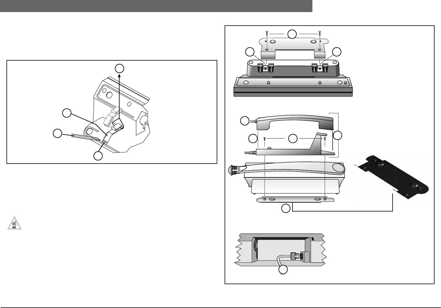
3.1.1 Removal cable guide (FIG 3-3) (Interpreter desk LBB 3520/10)
To access the cable guide proceed as follows:
1. Wrap a small cord round the cable guide and pull firmly in the direction shown.
2. Place the head of a screwdriver in the cable guide groove as shown and twist gently.
FIG 3-3 Removal of cable guide
3.1.2 Installing Intercom Handset to LBB 3520/10 (see FIG 3-4)
Handsets can be mounted and attached to the rear of an Interpreter desk LBB 3520/10, using a metal
mounting plate LBB 3556/00, screws and two spire speed nuts. The spire speed nuts are delivered
with the unit, and the securing screws are delivered with the mounting plate.
NOTE: When mounting the handset, spire speed nuts need to be mounted on the unit
after first removing the units cable guides (see FIG 3-4).
Using the available mounting facilities, handsets can be mounted for both left and right hand users. In
systems using flush-mounted units, handsets with cradles can be table-top mounted or fixed to an
adjacent wall using the screw-holes on the handset cradle.
FIG 3-4 Installing Intercom handset to an Interpreter desk LBB 3520/10
5
6
6
5
Underside Interpreter desk LBB 3520/10
Key to Symbols
1. Screws A
2. For mounting ‘spire’ speed
nuts
3. Handset
4. Handset cradle
5. Screws B
6. For flush and table top
mounting
7. Mounting plate LBB 3556/00
8. To intercom handset
LBB 3555/00
1
2 2
3
4 5
6
7
8
Interpreter desk LBB 3520/10
Interpreter desk LBB 3520/10


