2
Bosch Security Systems | 04-2003 | 3922 988 43318 en
Digital Congress Network | Installation and Operating Manual | Chapter 10 - Installation Techniques
en | 10-11
Stand-alone Systems
10.6.2 System layout (without extension units)
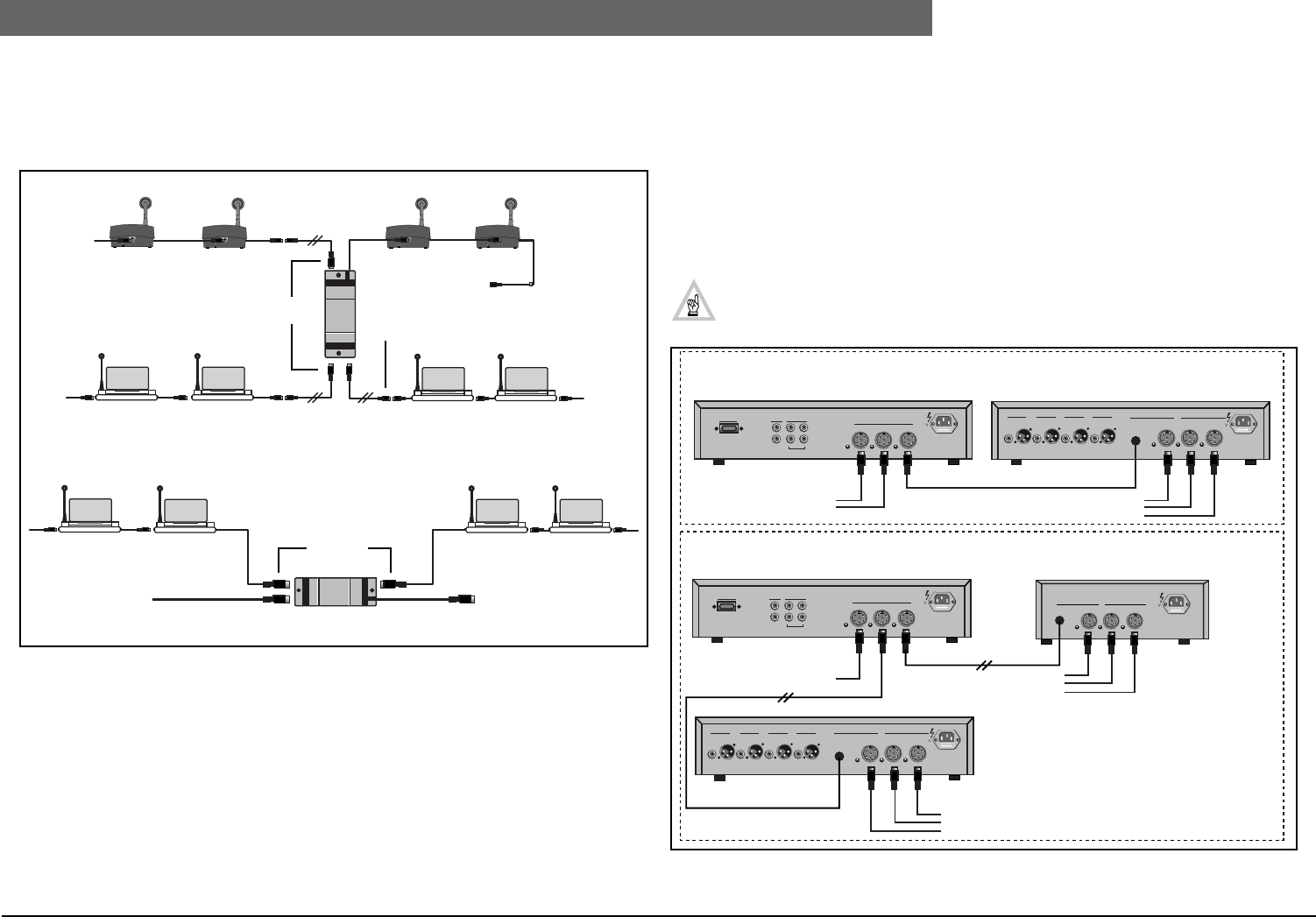
Using extension cables, Trunk-splitters and Tap-off units, the length of cable on a system unit can be
lengthened, and cable runs can be laid out in diverse directions. FIG 10-14 gives a typical layout
configuration using a Trunk-splitter and extension cables LBB 4116/xx.
FIG 10-14 Unit layout possibilities using trunk-splitters
10.6.3 System with Extension units
FIG 10-15 shows the Audio Media Interface unit connected directly to the Central Control Unit,
however in principle the unit can be connected to any convenient point within the DCN network
cabling.
The illustration shows a centralized configuration where all the DCNs Central Control equipment is
installed in a 19”-inch rack for example.
In a de-centralized configuration, the Extension Power Supply unit and the Audio Media Interface unit,
are placed in different locations separated from the Central Control equipment.
NOTE: The example below uses a Central Control Unit LBB 3500/05 having a total power
handling capacity of 90 PCF. Using a Central Control Unit LBB 3500/15 the power han-
dling capacity is limited to 180 PCF (max. 60 PCF per output).
FIG 10-15 Typical system interconnection
Tap-offs
To CCU
Trunk-line
Trunk-line
LBB 4114/00
Tap-offs
To CCU
Trunk-line
Trunk-line
LBB 4114/00
115
VT4A
230V
-
T2A
Output 1 Output 2 Output 3 Output 4 Trunk Tap-off
Port 1
Rec.
Line
In
Out
In
Out
Symmetrical
Trunk
115 V-T4A 230 V -T2A
115
VT4A
230V
-
T2A
Output 1 Output 2 Output 3 Output 4 Trunk Tap-off
Port 1
Rec.
Line
In
Out
In
Out
Symmetrical
Trunk
115 V-T4A 230 V -T2A
Trunk
115V-T4A 2 30V -T2A
Tap-off
In
LBB 3500/05
CENTRALISED SYSTEM
DE-CENTRALISED SYSTEM
LBB 3508/00
LBB 4106/00
PCF ≤180 (max.)
PCF ≤60 (max.)
LBB 3508/00
PCF ≤90 (max.)
PCF ≤90 (max.) PCF ≤90 (max.)


